A long time ago I created m2mMesh, which was an Arduino library for a self-organising mesh network onESP8266/32 that allowed you to do machine-to-machine messaging.
This has been quite useful but sometimes it's overly heavyweight so I've written a simpler thing for direct links between two devices. Also with just two devices you can use the built in encryption features of ESP-NOW. Lack of encryption was always a concern with m2mMesh.
This new library is m2mDirect, which I intend to use for control/telemetry of the various rovers I've been working on.
It's not in the Arduino Library Manager yet as it needs more work, in particular ESP8266 support and channel negotiation, but it is now available on GitHub.
For absolutely ages I've fancied building a remote controlled rover that's got some physical heft and can handle rough ground. I've never really been into RC cars but a 'robot' is different.
This urge goes all the way back to the 90s when I was a fan of the TV show Robot Wars and at one point I got as far buying some big AGM batteries and wheelchair motors but like with a lot of projects my enthusiasm fizzled out. Part of this was because back when I was first looking at it this was an expensive hobby. Good quality speed controllers, good RC gear and access to the materials and machine tools needed to build something (unless you worked for an engineering company or University Engineering dept.) implied a level of investment in time and money I couldn't really do. I eventually became friends with some people who had competed in Robot Wars but I never built a 'robot' myself.
Now we live in quite a different world.
Electric vehicles of all sizes are now commonplace; from RC quadcopters to commuter scooters, electrically assisted bicycles, motorcycles and cars. Developments in battery technology, brushless motors and semiconductors haven't only been technical improvements but also the cost/performance improvements that come from massive scale manufacturing.
Also, all manner of hobby electronics and computing has become hugely more affordable and accessible. I'm an active member of a Hackspace with access to all the tools I could reasonably need to make something viable and I've a bunch more free time than I used to have, at least for now.
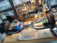
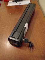
My recent trip to EMFCamp 2022 got me enthused again and while there I bought a 36v eBike 'Silvertail' battery pack as it's a well packaged large chunk of power with a built in battery management system. I've also dived in and bought some broken 'hoverboards' to play with.
The craze for hoverboards a few years back created a glut of cheap second hand ones, often 'dead' due to poor battery management making them refuse to charge. The same poor battery management also lead to a number of dangerous house fires, a reputation that still persists despite battery safety getting better.
Naturally, Hackspace people got hold of these and tried to do things with them.
The motors are very high performance for the bargain bucket second hand price and come with everything you need to drive them, maybe even battery packs if you can replace any dead cells without setting fire to anything. Good speed controllers are still expensive but the ones in hoverboards are kind of adequate.
Lucy Rausch worked out how to replace the original firmware for the ubiquitous controllers in early hoverboards and a whole load of people built comedy vehicles with them. A bunch of Germans are very into converting the popular children's ride-on "Bobby Car" toys into absurdly nippy little vehicles.
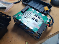
I've bought two of these 'dead' hoverbaords and even had a go at reviving the battery packs.
What could possibly go wrong?
There isn't a huge plan here. I just want to enjoy exploring how this works and as I'm coming at it after everybody else has already had a go there's plenty of information out there.
My minimum viable rover is just four hoverboard wheels, controllers and recovered battery pack screwed to a piece of plywood. This is not its final form, which may be six wheeled with rocker/bogie suspension in a vague Mars Rover homage.
The whole project has a bit of a 'what people were playing with 5-10 years ago' thing going on. It's not unexpected as where possible I'm using stuff I already have kicking around in the cellar.
Lacking any RC gear I made my own 2.4Ghz remote using a Wii Nunchuck controller which were ubiquitous in Arduino projects a while back and a couple of ESP8266 microcontrollers sending ESP-Now packets.
I ended up reasonably happy with the resulting code and might publish it even though it overlaps a bit with other published projects.
I'm also minded to play with a bit of collision avoidance and/or location mapping. Not to make the rover autonomous but to make it 'hard to crash into stuff'. This can advance separately from the chassis and basic remote control use. What was everybody enthusing about ten years ago that I had in a crate of junk?
The Microsoft Xbox 360 Kinect.
It's old hat, doesn't work outdoors in direct sunlight and getting old enough that support in modern versions of Robot OS might have disappeared enough that I give up on the idea, but I do have one and it does work as I've tested it with a fresh compile of the open source libraries.
I know in my heart I'll have to buy a proper LIDAR sensor (which like almost everything else have become massively more affordable) but in the meantime I can tinker with this.
So how far have I got?
Not massively far but I do at least have one pair of wheels moving.
Since the original explosion of hoverboard hacking the controller hardware has changed and you can't use Lucy's firmware, but various people have adapted it to the controllers they've found in their hoverboards or even started again from scratch.
One of my scrap hoverboards had controllers supported by one of these firmware variants, the other didn't.
A bit of peering at markings on the microcontroller suggests I could probably reverse engineer the board rework the pinouts and make my own firmware variant but that's going to be time consuming. So I've ordered another pair of identical boards to the supported ones. This was about the same price as another dead hoverboard but you won't know which controllers are inside until you open them.
As I've mentioned before, all the stuff I work on tends to be to make props for Live Action Role Playing (LARP) events. LARP comes in many flavours but the variant I'm involved in has people solving problems and fighting skirmishes with Lasertag weapons as part of a collaborative story, usually with a science fiction element.
With the arrival of the pandemic, almost all LARP except that which was conducted via video chat went on hiatus, including a game we'd been planning for a couple of years.
However things kicked off again for us on the weekend of 3-5 September 2021 with an 'anthology event' that consisted of several short games. After a chat with one of the game organisers I agreed to set up some stuff to round their Cyberpunk themed game out.
We play on exclusively outdoor sites, almost always with no access to mains power or permanent Internet service so everything needs to be self-sufficient for the duration of the game. Also with only a couple of hours of setup time available it needed to go out quick and dirty right beforehand.
I put together several elements that got included in the game, spread across three different locations on the site.
Long time no post, I've been kind of away from microcontroller project work recently. Having picked up coding again I've come across an interesting issue with ESP-Now on ESP8266.
It's not really an issue as such, but might catch you out.
Most of the time, when you send ESP-Now packets with...
esp_now_send(uint8 *da, uint8 *data, uint8 len);
...there's a temptation to assume they will always be sent.
However packets are not sent until the core gets around to it.
If your code does some slow blocking work after asking for the packet to be sent, the core will abandon sending the packet silently. You should instead register a callback function with...
esp_now_register_send_cb(esp_now_send_cb_t cb);
...and only continue with other activity, especially slow blocking activity, once that occurs.
My code was registering callbacks but as all it seemed they did was confirm a send I didn't really need confirming, the functions were stub ones where I'd commented out everything of note.
Most of the time this won't catch you out, but the timeout before the core abandons sending is rather short. A very dirty workaround might be to delay/yield for a short while after sending, but flagging the send as successful or not in the callback is the better option.
I had been struggling with unexplained packet drops in certain parts of my big ESP application and waiting for the send callbacks has eliminated these. A less I/O heavy application would probably never experience them.
I'm still slowly adding features to my retro computer terminal props and one of the things they lacked was a real-time clock.
So far I've been using 'mesh time' a millisecond uptime value that syncs across the mesh network.
I've now added the option for one or more nodes in the mesh network to share real-time clock information. This leverages the built in libraries for time that are included in the ESP8266/ESP32 SDK. It's just an offset from the mesh uptime with some simple logic to pick a preferred real-time source. Much like the mesh uptime it's not millisecond accurate, but good enough for human scale time, eg. the timestamps on chat messages. It also shares timezone information to correctly handle daylight saving.
At the moment I'm testing with SNTP (which is supported directly in the SDK) but my plan is it can take any RTC source. My code just checks "is the time set?" before sharing time so this should be trivial. this could include manually setting the clock from a watch, but I suspect it would drift fairly quickly. I'll attach some GPS modules onto a couple of my nodes for a time source in the field.
Prototype 5 sucked, trying to bodge in the ESP32-S2 breakout to the old board just didn't work well, so I did another prototype. Also as I now have the Nordic Semiconductor Power Profiler II, testing and measuring power use is so much easier and I could ditch the INA219 current sensors. These added a lot of mess to the previous prototypes.
As it's easy to adjust the voltage from the PPK2 it almost stands in as a dummy solar panel, although you can't current limit the output.
This latest prototype mostly came about because I designed a new schematic in EasyEDA, had a crisis of confidence about pin choice and how well it would work and resolved to just build it. Also it's Chinese New Year and I'm not in a hurry to order the boards.
I'm now absolutely set on using the ESP32-S2 for this project but I'll run this prototype off the panels for a few days and see how it behaves.
Update: I can't continue using the PAM2301 buck regulator I had intended to, testing showed it 'trips out' when panel voltage is ~6v. Which is fair enough given that's what's in the data sheet, but my expectation was charging load would keep voltage on a 5.5v panel below that, even though no-load voltage can be quite high. This is not true.
I've been doing lots of work on the flow of things in the user interface in the terminal application so it works better. The deeper in I get the more boilerplate I'm writing to make buttons appear and disappear without leaving stuff floating around, so it's quite slow progress.
On the plus side, the syncing of user accounts and so on is working nicely and I've now made it so that it live updates. Make a change to a user and it appears near-instantly on the other terminals. Previously it synced the files on the SD card but they didn't show until a reboot.
Actually coding that to happen took another swathe of boilerplate but each time I do a thing like this I'm edging closer to a believable looking application. Also a bit of bugfixing which might have finally nailed the occasional exceptions when using a mouse.
As it's getting closer to something I can demonstrate I did a quick show and tell on Brian Lough's 'Project Doc' stream this evening. Which I believe is recorded for posterity.
After generating some good data on power use of the ESP8285, I've finally got around to sticking an ESP32S2 into the same board using a hand-soldered adaptor based around a programming board. The board has LEDs on but I can probably account for this extra load. Mostly I want to know a rough equivalent power usage.
With a little tweaking of the code it runs fine, so I'll conduct a charge test over 24 hours and see what the graphs look like. If it's promising I may be migrating the project to an ESP32S2 because of the extra pin count and resources. Squeezing an SD card slot in along with the connections to the charge controller uses almost every usable pin the ESP8285 has.
Also, while I don't want to include a USB FTDI chip on the board, a spot for an OTG USB connector is another matter as by itself it uses no power. It would allow my board to also run CircuitPython, which is quite popular and were I to stick some on Tindie broaden interest I think. It's also a nice 'desk charging connector' and the 5V could go straight to the charge controller. The added component count would only be the socket itself and a resistor I think.
After the last test run, I decided I wanted to investigate the supply load tracking feature of the MCP73871 charge controller to see if it improves charging. With a small solar cell in winter, it will be very easy for the charging circuit load to drag down the voltage from the cell such that it ceases to be of use.
In order to see how well this works you also really need a good measure of the voltage and current at both the battery and the charging input. Which means adding the INA219 modules back again after I took them out.
Having considered reworking the previous board it's just too untidy and with the SD card reader attached the ESP8285 doesn't have enough pins to go around. Using socketed modules allowed me to just make a new carrier board and swap them over. I also made a big effort at tidier wiring, the last one was offensive.
The supply load tracking feature on the MCP73871 is called Voltage Proportional Charge Control (VPCC) and reduces load to the supply if the voltage drops below a threshold. VPCC needs a simple voltage divider that provides 1.23v (or more) at a pin while the supply is OK. If this voltage drops, it reduces current draw to bring it back up. On the new board I've fitted a small socket header so I can fit different values to the voltage divider.
We're also getting to the time of year where it might go below freezing and the thermal protection circuit needs testing. So I've added another header for the thermistor network, temporarily bypassed with a resistor while I fiddle with the VPCC in isolation. I'm going to move my test location to near an indoor window where there's more sun for more of the day and hang the solar cell out of the window. Once I've investigated the practical worth of VPCC I'll add the thermistor network and do some tests with heating and cooling it.
This time, I decided to build as close an equivalent as possible on stripboard despite the presence of several SMD-only components. For this I needed a QFN20 breakout and with the buck convertor, I used one of the first boards I had made, cutting off the large empty sections. The QFN20 was not fun to solder but it works.
I'm glad I went through this step as it showed up a poor selection of GPIO pins for the connection to the MCP73871 charge controller. My very first prototype used an evaluation board and not all the connections are broken out on it. Moving the status connections to the ESP8285 did what I wanted but dragged one of the pins low and stopped it from booting in some states. This is one of those things that again I should have picked up from reading the datasheets, but didn't.
With a little shuffle of pins, the prototype is ugly but seemingly nicely functional so I've dropped it into the shed to test. Late November is a bad time for solar power in the UK, so it's a bit of a 'torture test' of charging viability. It's quite likely to fail as I've not put much in the way of smarts yet about when it sleeps or switches off the radio.
In the meantime I've bought an ESP32S2 module and breakout adapter from a Tindie seller. I may build a second prototype based around this as the S2 is like an ESP8266++ with Bluetooth support and lots more resources without seemingly much more power draw. The extra GPIO pins won't be unwelcome too, the ESP8285 has few and I've ended up re-using the UART pins. Not a big deal but it means you can't have Serial debug info with the charge controller working and you need to rely on OTA updates after an initial upload of the code.
Update
This prototype ran for roughly 66 hours before the battery got low and it started sleeping in an attempt to allow the sun to charge them. That's plenty enough for my requirement of a full weekend's service.
However, from the logs it looks like it only spent 4 hours actively charging the battery, which is shockingly low even given its shady position in the low winter sun. As the MCP73871 only has three binary status indicators I don't feel I have enough data to be clear what contribution the solar panel was making to the runtime so I am going to modify this prototype and add an INA219 current monitor inline with the battery.
I received the new boards from JLCPCB and they look great, but I've made a real rookie mistake when ordering.
Working in EasyEDA, component selection defaults to 0201 packages for things like the resistors.
These are tiny. Really really tiny.
This is something I already knew and just missed it when laying out the board.
I realised my mistake when ordering the components but thought, let's give it a go. I have made an attempt to solder these but with my ageing eyesight I can barely see and handle them, let alone apply paste and hot air to successfully solder them.
Now with the ongoing pandemic I don't have any immediate application for these boards, so I'll pause a little while before coming back to them and producing a new version. Either I'll choose larger components or have JLCPCB do PCB assembly for me, which is increasingly affordable.
A chunk of my work has always been about building things with microcontroller boards (either classic Arduino AVR or ESP8266/ESP32) that you interact with directly.
For our (postponed) LARP event in March I had created a fake 'computer terminal' that you interacted with, where all the work is done on an ESP8266. RFID cards log a user on and there was a chat application, file viewing and so on, all using my ESP-Now mesh network to allow the individual terminals to send messages to each other.
In order to make this I used ANSI/VT100 escape sequences to create a very simple 'application' that you accessed using a terminal emulator, PuTTY, running on old laptops.
It's not wrong to argue this is the 'tail wagging the dog' when there's a much more powerful computer just running PuTTY but the guiding factor was the mesh networking, not the application itself. It also meant anything you could run PuTTY on could quickly and easily be pressed into service as a terminal and PuTTY is available for Windows and Linux. Likewise any other terminal emulator that supported a broad range of terminal capabilities could be used, but all my testing has been with PuTTY.
In the weeks before the event, I was in a 'crunch' working on various props and technology for the game 14+ hours a day until suddenly we postponed due to the pandemic.
As irritating as this was it's given me time to turn this work into a re-usable Arduino library. Such things already exist to place the cursor, change colours and so on but the one I've been working on has 'widgets' like mouse-clickable buttons and does the work of drawing/updating them for you.
The idea is if you have an Arduino project that needs a user interface, perhaps one that's infrequently used, you can build this with minimal pain. Then to access it you just connect a USB cable and there's a terminal UI available over the serial connection. Sadly it does not work in the Arduino console monitor as it's not a proper terminal application, but PuTTY isn't onerous to install.
I have an aspiration this would be usable over the network on microcontrollers with Wi-Fi such as the ESP8266 but it probably has more value on those without. If you've got Wi-Fi, basic web server front ends are going to be more flexible.
After over two weeks continuous running my first prototype of the solar charged prototype proved itself with a 2W panel. So I spent a chunk of time designing the next iteration in EasyEDA and ordered five PCBs from JLCPCB in China.
I've taken a small gamble with this design as I haven't built it on breadboard first and have added a number of new features.
Thermal protection for the 18650 cells, a feature available but omitted from the MCP73871 evaluation board. They will now only charge in temperatures of 0-50C, which is a default safe option. I don't feel this will kick in often in the UK except perhaps on a very sunny but cold morning however to omit this feature would be slightly negligent.
Replacement of the INA219 current monitors with a simple resistor ladder to measure supply voltage after the charge controller with the ESP8285.
Connection of the MCP73871 status pins to the ESP8285 rather than indicator LEDs.
A microSD socket for optional file storage.
This is quite a simple project compared to the people making their own small board computers or things based on FPGAs but it's only my second ever manufactured PCB. All the pins on the ESP8285 board are in use, although in principle IO0 which has a button attached for putting it into programming mode could be doubled up with for something else so long as it defaulted to a pullup.
Instead of going straight to the final run of boards I'd like to test these five before ordering more. I made absolutely no effort to keep it compact so even if no changes are needed I'll still move things around and tidy it up before the final order.
Once these arrive I'm hoping the extra efficiency of the PAM2301 regulator will make a 1W panel viable in the UK but if not, 2W panels aren't overly huge.
A bit of data logging showed a single 1W panel useful for supplementing battery power to my mesh network node, but not really enough to charge it meaningfully at the same time. My garden is south facing and the house blocks direct sun lots of the day so it was only the few hours where the panel was in strong direct sun that the result was acceptable. For something that spends a lot of the time asleep this would be reasonable but as I want each node to run for all the waking hours then I need it to do better. I did get 52 hours of runtime, which is technically enough for my needs if I fit two 18650s in the node, but I still don't like the thought of it running down constantly with only a tiny amount of headroom.
The data also shows the regulator board I took out of a drawer is an LDO, not a buck converter, so it's 60% efficient a lot of the time. I will make a pin compatible replacement with the converter I specified for the final boards and that should be a big help.
I've now set up two 1W panels in parallel to make an effective 2W panel. Only a few hours later it's clear this makes a massive difference as they spend lots of time charging the cell rather than just 'treading water'. I'll leave the test to run until the battery protection kicks in at 3.5V but it looks like 2W panels really are what's needed even if I were to replace the LDO. There are some really quite affordable 2W 5.5V cells on Banggood, so going up in size isn't a big deal.
After a little fiddling around today I had software on ESP8285 node so I can keep track of the battery use and how well the MCP73871 manages things.
Working at my desk it seems to seamlessly charge then swap over to battery if needed, but more importantly if there's roughly 0.5W charging capacity, which is what I'm expecting from the solar panels I have, available it'll run the ESP8285 and use excess to top up the single 18650 I've fitted for now. This is exactly what I was hoping for from the chip, but what's not clear yet is how well it works around dawn and dusk. Playing around with my bench PSU would give me some idea but with solar cells varying voltage under load I've just gone straight for a practical test.
The code I've put on isn't anything like the final application but it does sit there connected to WiFi pushing data to MQTT every 30s so it's a pretty reasonable test. I'm dropping the output into a .csv file on my server and I'll look at it periodically to see how the battery fares. As I wanted real timestamps on the data I used the quite nice ezTime library to sync with NTP but more importantly maintain a usable time based off the ESP8285's internal clock and only periodically update it. This is a feature I will need when things happen for real, although I'll probably have to use GPS and a local NTP server due to lack of guaranteed internet access.
Also Blogger has changed and all my layouts are broken. Sigh.
Putting a 'production' board together rekindled my interest in a solar charging prototype of my mesh network nodes.
A small solar cell in typical UK weather is not going to be able to run the node 100% of the daytime, but it will almost certainly work as a useful 'runtime extender'.
I started looking at this way back last autumn then like a lot of things my enthusiasm waned and it languished in a box for months. Today I finished off putting it together to a point where I could knock some software up and start logging charging/load data.
I'm using the same ESP8285 module I have for the nodes, with an MCP73871 development board for charging and power management. The naive approach would be to stick a conventional LiPo charger in parallel with the batteries but the load messes with the charging.
The MCP73871 manages the power path so that depending on the charging power available it will run the load from that while also charging the batteries, run the load from it, or once it it is too low run the load from the batteries. As the battery isn't directly connected to the load this can be done while maintaining proper charge behaviour for the LiPo. It is not proper MPPT tracking for the solar cell, but it does sensing of how much current it can draw before the voltage drops too low that will have a similar effect. For extra efficiency a DC-DC converter that does MPPT would help, but I'm going to suck it and see if this prototype is 'good enough'.
I've shoehorned several INA219 current/voltage sensors into the power path so I know the battery, charging and load detail. My plan is to stick this inside my shed, with a solar cell outside and simply log the data until it falls off the network because the MCP73871 has decided to protect the battery.
Back in February I was faced with a looming deadline for our LARP in March where we would be using my ESP-Now mesh network for messaging between props and also to end devices used by players.
For this to work we'd need some fixed nodes to give minimal coverage. I had previously built ten static nodes using Wemos D1 mini Pro boards and NiMH batteries and used them in testing but battery life was only around eight hours which wouldn't be enough even with overnight charging.
I did a few sums, came up with a power budget and figured something with a more efficient regulator, no indicator LEDs and a couple of 18650 cells in parallel should easily run for a whole weekend, eliminating another point of stress for the game.
Scratch building all this would have been a drag so I designed and ordered twenty boards from JLCPCB in China.
I had previously tried designing boards in KiCAD but found the interface impenetrable even for simple things and got deterred. For these boards I tried out JLCPCB's own web based EDA software, EasyEDA and was pleasantly surprised.
While I did have a bit of a struggle finding matching footprints for the components involved the process really wasn't hard. They also integrate this fairly tightly with the PCB ordering making the generation of gerber files, drill files and so on something you don't need to worry about too much.
This smoothing over of the complicated process meant I was able to get to grips with EasyEDA, design a board and order it in a morning with my only previous experience being a couple of failed attempts to do something useful in KiCAD.
Sadly with the postponement of our game due to the pandemic these boards have sat on the side since delivery but today I finally built one and it works! I added a reset switch to make repeated programming easier, and were I to design them again I would add a reset and flash button on the board, but for now these suffice. There's almost nothing to the circuit, it's an ESP8285 module, buck regulator, battery holders and some headers. No charging or protection circuit and nothing to leech power that isn't needed.
Until I add more features I have in mind like onboard solar charging then they'll do. In the meantime I'll do some current measurements and rundown tests with this one to check its performance. I'm really hoping these will give us the coverage we need for the game and now I've some more time to work on it I can actually check properly.
The library has an option to turn the RFID antenna on and off. Simply shutting it off and turning back on to check the card periodically seems a 100% stable solution.
Obviously you should also check the card hasn't been swapped by checking the ID hasn't changed but here is a a minimal sketch to do this. As checking for a card stops it appearing as new it's easy to get the logic messed up but this is a tested and working example.
Note to self: start putting stuff on GutHub.
#include <SPI.h>
#include <MFRC522.h>
const uint8_t SS_PIN = D8; //My example code is for a WeMos D1 mini, change these to match your setup
const uint8_t RST_PIN = D0; //My example code is for a WeMos D1 mini, change these to match your setup
MFRC522 rfid(SS_PIN, RST_PIN);
bool cardPresentWhenLastChecked = false;
bool antennaEnabled = true;
uint32_t cardCheckTimer = 0;
void setup()
{
Serial.begin(115200);
SPI.begin();
rfid.PCD_Init();
Serial.println(F("Checking for RFID card removal"));
}
void loop()
{
if(millis() > cardCheckTimer)
{
//Start a check of the card
if(antennaEnabled == false)
{
//Turn the antenna back on
rfid.PCD_AntennaOn();
antennaEnabled = true;
//It takes time to wake up the RFID card so the sketch needs to wait before checking for it
cardCheckTimer = millis() + 20ul;
}
else if(antennaEnabled == true)
{
if(millis() > cardCheckTimer)
{
//Check for a card after a delay for it to power up
LilyGo are known for producing a lot of 'maker friendly' development boards where they cram a lot of useful stuff together on a board in various combinations, lots of it based around the ESP8266 or ESP32.
Chances are there's a combination that might not be exactly what you want, but close enough you don't need to build something up from scratch or a tangle of different modules. Want an E-paper display, OLED display, LORA radio, Cellular connectivity, LiPo charging circuit and ESP or some random combo of 2-3 of these on one board they probably make it. It's all cheap and cheerful AliExpress/Banggood fare and I've bought a few things from them over the years.
This here is closer to an actual product, it's a 'fitness band' looking much like one of the sea of cheap BLE ones available for attaching to your phone but it's maker friendly with a programming cable and apparently usable code for all the components on GitHub.
Based around the ESP32 it's probably not the best platform for something like this as it's too power hungry, but it should be something I can program myself.
I have plans to tie it into my mesh network and directly deliver messages over ESP-Now with no need for a phone.
This is a kind of speculative purchase, I may not find the time to get the code in order for when I need it, but it was cheap as chips and if it does work it will be great.
After a chunk of work I've got file syncing working fully. The code does a simple manifest of everything on the SD card except for the irritating "System Volume Information" directory Windows puts on there if you view the card on a Windows system.
As my mesh network isn't designed to be high bandwidth and I'm not expecting the files on there to change often, this is a slow, lightweight process. After all it's only running on an ESP8266, don't expect BitTorrent.
The steps the mesh takes to sync are broadly...
Recursively iterate the whole file system on the SD card
Open each file and do a CRC16 of it
Store the full path and filename, size and CRC16 in a data structure
Write this to a simple flat file to save this across restarts. Each file is given a sequence number starting at one that increments with each change
Once all the files have been read, XOR all their CRC16s together and store it
The total number of files and this XOR of the CRC16s are advertised periodically by each node flooding the whole mesh
If a node receives a XOR that doesn't match its own it asks for the CRC16, size and sequence number of each file on the other node, one at a time
Some simple if/then/else logic decides if it needs the other node's version of the file
Files are transferred 64 bytes at a time in a TFTP-esque manner
Once the XOR and number of files match the two nodes are considered synced and stop
To detect change from an initially synced state, if a file is changed the new CRC16, size and sequence number are flooded to the whole mesh immediately
Notification of deleted files use a similar mechanism and stay in the data structure
There are timeouts and retries on the various steps in the process so it will fail fairly gracefully and restart
This is probably full of edge case horrors and has no way to handle file conflict resolution. I don't care, this is not an enterprise class distributed file system, it's a bunch of microcontrollers in a field that I need to have the same files on, mostly, and stay in sync, mostly.