Hoverboard motor powered rover: Part 6

Things seem to have slowed down with work on my rover as I keep disappearing on 'side quests' and one of those was to make a better controller for this and any other projects that need a remote controller.

So I cooked up a 3D printed design with some 3-axis sticks and as many buttons as I could manage on an ESP32. It's partly inspired by the 3D printed controllers James Bruton and Keegan Neave have made but ESP32 based.

With a screen I happened to have fitted and the encrypted 2-device ESP-Now library I'm working on being bidirectional (another side quest) it should be able to give lots of info on the rover while it's in use like battery voltage, location and so on.

This might be of use to others (although the design's quite specific to that screen) so I've made it available on GitHub and christened it Sticky.

LD2410 radar sensors

As I worry about safety around my rover I've been looking for a way to detect people that doesn't rely on anything complicated like AI image analysis and can be done with a simple cheap sensor.

By chance, Andreas Spiess did a brief review of the new Hi-Link LD2410 24Ghz radar sensors, which are designed for presence detection.

They look promising and aren't expensive, so I bought a few along with the dedicated UART breakout board made for them.

My little bit of testing suggests they're really quite good at detecting people within a few metres, whether they are moving or not and people are rarely completely still. At close range it can tell if you're breathing.

While you can just connect one of the pins to a GPIO to signal presence they use a serial protocol for configuration and more detailed readings. However as they are comparatively new devices there wasn't a library for this.

Between reading the work somebody has started on integrating them into ESPHome and the slightly confusing manufacturers datasheet I've cooked up an Arduino Library and submitted it to the Library Manager. I hope people find it useful.

Now I need to make some breakouts for them, they use 1.27mm headers, and attach them to my rover.


Hoverboard motor powered rover: Part 5

I've slowly been chipping away at adding sensors to the rover and it's at a point where I really need to dig deep into RobotOS (ROS) and start on tying it all together.

The Wyse 5060 thin client has been screwed to an old VESA TV bracket, which works OK but tends to come loose under vibration. Given I primarily want to make the rover drive around outdoors this urgently needs fixing.

The Kinect has been cut down, using information from this blog post so it can be screwed directly to the top deck and this works really well.

I threw a bit of effort at software and the sonar range finders are now an I2C peripheral of the Wemos D1 Mini that talks to the remote control and sends commands to the motor controllers. I also found an old MPU6050 accelerometer and a nice tilt compensated compass to give reliable orientation information put these on the I2C bus.

The 5060's original SSD was too small to be practical, being only 8GB. I happened to have a larger one in an unused machine and bought a cheap adaptor to make it physically fit, so the onboard computer's now running a full copy of Ubuntu and it's possible to remote desktop into it and test the Kinect 'live'. A couple of USB WiFi dongles, while not ideal connect it to my home network indoors and provide a 'hotspot' for working on it elsewhere.

With the D1 Mini connected over USB to the the 5060 it should be possible to use rosserial to pass all I2C connected sensor information and detail from the motor controllers sensors back to ROS, while accepting 'twist' commands to move. I do vaguely wonder if I should move to an ESP32 though, as the D1 mini is rather busy with synchronous tasks that could do with being done on a second core but more importantly having hardware UARTs to talk to the motor controllers would be far better than the software serial library I'm using.

I've also plugged a USB GPS dongle I had in my box of project bits into a spare port.

Which means I've close to a full 'sensor suite' for a basic rover. The Kinect won't work outdoors and the GPS won't work indoors, so I still need to come up with something to cover these complementary gaps and do a load of work on sensor fusion, but learning about this topic is the whole point of this project.

I see LIDAR and custom made wheel tick sensors built into the hoverboard motors in my future. The former will give some outdoor obstacle location for mapping and the latter help with dead reckoning indoors. Dead reckoning is not going to work on loose surfaces, but will do OK on nice indoor flat floors and be backed up by the Kinect.

As this very much got me to a solid milestone on the rover, I've christened it with a name, 'Crufty' as it's made from 'maker cruft' and intend to write up/open source large chunks of it on Github.

It was also an opportunity for a presentation at my Raspberry Pi meetup despite the total lack of Raspberry Pis in the build.


Making ESPUI a captive portal on ESP8266/ESP32

There's a really nice UI for making basic interactive web applications using the Arduino IDE on ESP microcontrollers, ESPUI. This is a real shortcut to usability for very basic "push a button a on web page and something happens" projects as it works asynchronously and does all the behind the scenes dirty work for you.

It does have one dull limitation though, it doesn't by default work as a captive portal. You can bodge a fix to this with the following steps.

First, find the line in ESPUI.c

server->onNotFound([](AsyncWebServerRequest* request) { request->send(404); });

Then comment it out and add the code

server->onNotFound([](AsyncWebServerRequest* request) { request->redirect("/")});

This means any time a request for an unexpected URL hits the Web Server on the ESP it will redirect to the root of the server. You can change this to some other URL by changing the "/".

Now this still won't get all requests to hit the ESP, you need to add the following bits into the rest of the sketch. This assumes your ESP is acting as an AP on the usual IP address 192.168.4.1, but you can see how it's easily changed.

<near the top of the sketch>
#include <DNSServer.h>
IPAddress apIP(192, 168, 4, 1);
DNSServer dnsServer;

void setup()
{
    <rest of your setup stuff>
    dnsServer.start(53, "*", apIP);
    dnsServer.setErrorReplyCode(DNSReplyCode::NoError);
}
 
void loop()
{
    <rest of your loop stuff>
    dnsServer.processNextRequest();
}

I really should submit a more complete solution as a pull request and new example to the library.

Now when most devices hit the ESP they will take you straight to the page asking you to "sign in" etc. and it doesn't stop you manually going to the page.

Quick cyberdeck build: Part 9

This is an after action report on the Cyberdeck as the LARP I put it together for was this week. It worked excellently with a couple of minor irritations.

In advance I had worried about the battery life being poor as I'd never really done a run down test and it was fitted with a cheap eBay aftermarket battery. Also, hanging the keypad, trackball and illuminated buttons off USB OTG was using a little power all the time despite using my Power Profiler to help reduce that as much as I could.

In the end it was just fine to be used heavily all day. There was a lot of in-game chat.

I had wondered about usability as modern smartphones and their apps are designed around a touch interface with really great predictive typing. 

Going back to a trackball, mouse buttons and keyboard is very much a retrograde step. Discord (which the LARP used for in game communications) did suck a bit with the non-touch interface but was usable and the case fitted nicely in both hands for two thumb typing. The screen could still be touched but this is hard near the edges due to the lip on the case.

The biggest aggro was the paint. I hate painting 3D printed objects and having tried not to spray the paint on too thick and give it plenty of time to dry the red parts were still soft as I was travelling to the game.

At various points the case, especially the back, kept sticking to other things like the tool belt I carried the Cyberdeck in. You can see this quite clearly in the second photo where it's messed up the finish. If I ever open this up again to add more features, like a LORA radio, I'll end up reprinting the case and transferring the internals to a new one which will mean ungluing some of the wiring.

Quick cyberdeck build: Part 8

Some nine months after I started this 'quick' build it's done.

Nothing unexpected slowed me down really, but the level of accuracy needed in modelling the 3D printed enclosure ate lots and lots of time and test prints. I also faffed with not finalising how the charging would be done and having to swap from USB OTG host to USB charging and this led to reprints of the back section of the case.

There's now a slide switch on the bottom that swaps from charging to enabling USB OTG next to the USB socket.

Painting 3D prints is horrible and I hate it. I don't know how cosplay people deal with all the faff. I guess them shifting heavily to resin printers even on things without masses of detail tells you everything you need to know about how awful finishing FDM 3D printed stuff is. The final result on the top fascia is great but I really can't justify it on most of my one-use props. The back didn't come out as well but you're not looking at the back much.

The device is obviously a massive inefficient use of space compared to the phone I built this around but that would be missing the point.

I've also decided that there's room inside this one for an RFM95 LORA module to make a LORA messenger, which would be quite cool but it'll have to wait until I've got time to make a second iteration of this. I'd also like to fit a USB hub and the option to plug in USB flash drives etc. A full size USB socket is quite chonky but there might be scope to squeeze one in.

I'm assisting running a Cyberpunk LARP in a month or so and wondering about reworking the 'cyberdecks' I made for the previous instalment of the game. They are just big 3D printed carry cases for Nexus 9 tablets which I've settled on as my standard "issue a tablet to LARP players" tablet because they're cheap and decent. 

The game semi-requires of attaching stuff to the 'cyberdecks' with USB OTG cable at one point and once you start down that road adding random buttons and a keypad gets very tempting.


Hoverboard motor powered rover: Part 4

With the arrival of more Kinects I need to get back to mounting a computer on the rover in a better way than just cable-tying a Raspberry Pi to a cable-tie base. It was rattling round like a mad thing outdoors which was just generally unsatisfactory.

Having read up a little on ROS I came to the conclusion that I needed a more powerful computer than a Pi 3B+. The Kinects chuck a lot of data at USB, the Pi3 hangs everything off USB and poor performance of USB peripherals is a standard Pi thing. If I want to try the Xbox One Kinect it requires USB3 which the Pi3 simply doesn't have. However with the ongoing chip shortage you simply can't buy things like Pi 4s or Jetson Nanos easily.

To get something with a bit of grunt and more memory without breaking the bank I took a leaf out of Colin Hickey's book and bought a used thin client from eBay. This one is a Dell Wyse 5060 which gets you an AMD GX-424CC quad core 2.4Ghz processor, 4GB RAM, USB3 and a tiny 8GB SSD for £37 delivered. A quick rummage in my box of PC parts and I found another SODIMM so it's now sporting 8GB of RAM. There's a well know pre-set password of 'Fireport' on the BIOS and once you've cleared this you can wipe the SSD and install any desktop OS you fancy.

Ubuntu 20.04LTS, the main supported OS for the final release ROS 1 'Noetic' fits on the 8GB SSD fine although I can imagine running out of space at some point. The SSD fitted is a weird stubby SATA thing plugged directly into the board but apart from the physical form factor it seems it's otherwise standard SATA. So if needed I can make an internal cradle and connect a standard drive with SATA cables.

It's a really nice little machine. I booted a LiveUSB of the Ubuntu desktop and it's really quite nippy for the basic specification.

Being a thin client the case has proper mounting points for both a VESA mount and a desktop stand. It just fits on the deck of the rover and I can see myself using the VESA mount for this. It's fanless and DC powered with a ubiquitous 19V laptop style supply and I should be able to use a buck convertor to get that from the rover's 36V battery pack easily. Physically it's about 5-6 times the size of a Pi in a case but given the scale of rover I'm building this isn't a big deal.

The only concern is this will use a lot more power than a SBC like a Pi or Jetson but it is far more efficient than a full desktop, it's effectively laptop style components. It's missing the optional WiFi adapter but I'm not bothered by that. I've got some USB ones and with six USB ports on two separate buses that's not going to kill performance for other things.

I'm really impressed with the build quality, silence and compactness of this little thing, it's almost tempting to replace the hulking ancient desktop I use in my cellar workshop with another Wyse 5060 the same. I'm not even sure it'd be any slower.

Quick cyberdeck build: Part 7

I've been worrying about the charging of the battery for the Cyberdeck and my naïve idea was to simply stick a TP4056 charger inline with the battery. This sort of worked and when I fitted the new battery recently I checked it was OK, but the behaviour of the phone and the labelling on the pack gave me pause.

For a start the phone doesn't know the battery is charging. This sort of doesn't matter but you've also got the issue the charger doesn't know when to stop charging if the phone is switched on, due to the load from the device. This is exactly the sort of stuff I get fussy about in other projects and it's nagging at me that I was not practicing what I preach.

Also the TP4056 is set up for a slightly different chemistry cell with a 4.2v charge voltage. The battery I received has a 4.35v charge voltage and a peer at the images for these Motorola replacements shows they're all the same.

You can't change the charge voltage on the TP4056 it's preset.

This put the nail in the idea of just sticking that TP4056 charger inline and I'm back to charging it via the phone. Which is precluded by the OTG USB needed for the keyboard and trackball.

So I need to make it switchable.

For USB OTG to occur, the usually unused ID pin on the micro USB connector needs to be connected to ground. When this happens it turns the phone into a USB host and it starts supplying 5v on the VBUS pin normally used to charge the phone.

Once in USB OTG mode you can't charge the phone and supplying 5V on VBUS doesn't achieve anything. If you switch out of USB OTG mode while supplying 5V on VBUS with a device still attached this particular phone cycles from charging to not, which I'm not sure is expected behaviour or not but it's what I've got to deal with.

I've done a practical test to verify all this and using a couple of switches means you can swap from charging to USB OTG reliably. I'm sure something could be done with a few MOSFETs to effect the required swaps when you connect a charger but for this project I'm just going with a DPDT switch made out of two small SPDT switches mostly for time reasons. This has the added benefit of allowing me to completely disconnect the USB peripheral if I want.

So I've got to remake the little flat USB OTG cable I made and rework the whole thing, but I think it's worth doing slightly more properly than I'd planned.


Hoverboard motor powered rover: Part 3


I finally took my rover down to East Essex Hackspace and drove it around a bit.

This showed it to be fairly easy to drive with the ESP-Now Nunchuck remote control and the range is more than I need for basic testing.

At its lowest speed setting the rover doesn't always make a lot of purchase on the uneven ground as it's prone to wheel spinning, but as it's 4WD it always makes some progress. This will be massively helped with some form of suspension.

Four wheels screwed to the corners of a piece of plywood is not an optimum chassis design once the surface is anything less than super smooth, but I knew this when I did it.

On the higher speed settings it digs in, gains momentum and flies about, rattling as it goes. The Kinect shook off of its 3D printed mount and I could hear the cable-tied Raspberry Pi rattling like mad so these things need securing in a significantly better way. I'm building up to stripping down the Kinect and making a custom enclosure of my own.

For the test I was using the 'best' of the three battery packs salvaged from the hoverboards and it lasted just fine.

There's not much else to say about this test but here's a little video I recorded.


Quick cyberdeck build: Part 6

Today I received the replacement battery for the cyberdeck and fitted it after modifying the leads so I can insert the external charger between battery and phone. I'm still not 100% happy with this setup but it works.

The interim result is really quite appealing but the paint is still not 100% dry and as I need to handle it a lot doing the last parts I'm going to shelve any more work on it for a couple of days. It's gloss paint so still very slightly soft and I bet it actually takes a week to dry.

Designing the bumpers has got a little mired in lack of vision for what they should look like and some difficulties there'd be in printing and painting the sort of ribbed look I originally wanted. The OpenSCAD design has got very messy with little tweaks to locations and dimensions all over the place in the code so making anything line up nicely is hard. I need to resolve this soon as it will be a long print that also needs painting.

Quick cyberdeck build: Part 5

Quick? I don't think so.

With no immediate use for my Android Cyberdeck project it got shelved for almost a year but now I'm off to a LARP next month that is using the Discord app. for in-game communications.

So this came back out of storage and progressed somewhat.

To make the XBox 360 chatpad and the little Pimoroni trackball work I've made a custom short flat USB OTG cable by cutting up one of the OTG adaptors I had (so it had the extra pin shorted) and mating it with a micro-USB plug scavenged from a cable. Yes you can buy these things but I'm not in the habit of making my own USB cables so I don't have the parts hanging around.

There's a small nub sticking out of the side of the current enclosure but it's getting cosmetic 'bumpers' I'll use to hide this.

The redesign for more buttons has gone OK. There are now three illuminated tactile buttons which I'm hoping I can make use of for dedicated forward/back as well as the usual click. I could almost do with some more because Android has a surprisingly pleasant mouse button interface that you don't normally experience because frankly how often do you connect a mouse to your phone? I might try and implement some buttons in the side that take the place of a mouse scroll wheel, but it'll be fiddly to physically mount them.

The huge battery in shot is just for testing it's far too big to work in the final thing, I think I'm going to order a replacement for the OEM battery as it's a perfect fit. Tucking the added electronics into that space was the original plan but a nicely fitted battery is more important.


Hoverboard motor powered rover: Part 2

One of the features I really want to play with in the rover is some kind of location awareness combined with obstacle avoidance.

There are a lot of ways to do this of varying effectiveness based on the situation.

In one of my many boxes of maker junk I had an XBox 360 Kinect, which like the hoverboard was a thing lots of people threw time at hacking several years ago.

The 360 Kinect is old hat now and more modern sensors do more but I've got the Kinect. More importantly if I want to do things like cut the cable down, remove the case to slim it down etc. etc. they can be had for less than the cost of postage on eBay. So I've bought second one and it's on its way.

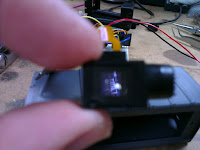
The Kinect is a combination of a decent conventional RGB camera, infrared camera and an infrared projector that throws a mass of points of infrared light at the scene. Onboard processors then turn that into an RGBD (red/green/blue/depth) image by mapping the distortion of the infrared dots.

The problem with old open source software is much like old closed source hardware: it stops working.

Not in the fact it's fundamentally broken but the shifting sands of time and internet entropy means once it's no longer heavily maintained and interested people move on links break, software versions change and stuff gets deprecated.

You can still install it from binaries. The SBC I actually wanted to try the Kinect with installed them just fine but then it failed to work with no obvious error.

Moving on to a laptop running a different Linux variant the binaries installed and worked but without sound. The Kinect firmware is missing from the binaries. The firmware is a Microsoft blob of proprietary stuff so that's understandable but the script to download that firmware is missing too. I don't have an immediate need for the onboard microphones but it irks me.

So I shifted to building from source and the instructions are wrong.

Not hideously wrong but links to libraries and git repositories were wrong or out of date and some default installed utilities needed are no longer there. So I muddled through and got it built. If I have a second go at building it, which is inevitable, I'll try to write it up and correct the OpenKinect Wiki.

My being able to correct these problems is one of the strengths of open source software but I fully understand why a lot of people find it frustrating. When I first got the Kinect out of the box it's been lurking in for several years to prove it still worked I installed the Microsoft drivers and developers kit on Windows 10. The Kinect immediately gave results ten years afters release. It 'just worked' in the way everybody moans Windows doesn't.

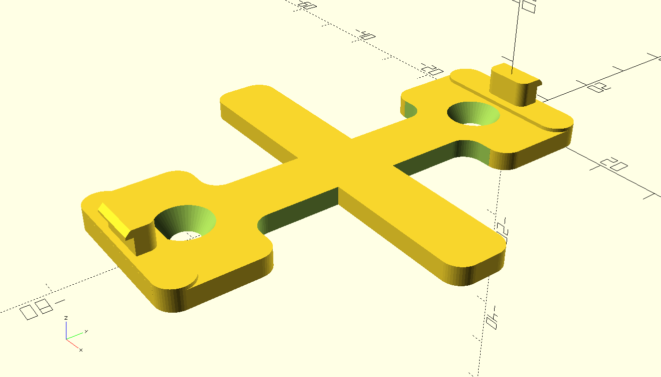
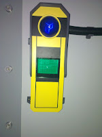
In parallel with this I've been wondering how to mount the Kinect so as per usual it's 3D printing to the rescue.

I didn't like the look of any of the mounts found on Thingiverse (one of them I tried just didn't fit) so I designed my own. Making very specific module/object mounts for prototyping things seems to be a thing I spend a lot of time doing. The end result is quite nice so I've uploaded it for other people to use.

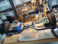
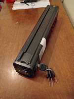
I've now made a 'deck' on top of the rover that protects and hides the messy motor, driver, battery and power supply wiring. The battery puts out 31-40v but I need 5v and 12v (maybe 3.3v too) buses to drive the control stuff and this wiring begins to take up a chunk of space. There's also on/off switches, battery isolator, charger connections and so on. Deck is a fancy word it's just another bit of plywood  from a skip with stuff screwed to it haphazardly.

First on the list screwed to the deck was the Kinect on its 3D printed mount.

The thing with the Kinect and frankly any other kind of RGBD sensor is they are quite 'heavyweight' sensors in terms of processing power. You get depth information but it's not an easily digestible map; it has to be processed extensively to act on.

This is on top of all the limitations the sensor has physically. It just can't be relied on to reliably prevent collisions etc., even before you allow for any mistakes in my coding and setup.

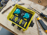
If you look at almost any autonomous vehicle they will have a whole suite of sensors to keep things safe and to that end I've made an array of three old-school ultrasonic range finders on the bottom of the rover in another 3D printed enclosure. They fit quite nicely between the two motor mounts.

These ultrasonic sensors are decades old tech but you still find them in beginner robotics projects because they're cheap and highly effective at short range. They too have limitations, but should be an OK backstop for making it harder to drive the rover straight into a wall or perhaps more importantly into somebody.

Running these ultrasonic sensors is an old-school Arduino Nano, which frankly is perfect for this task. I may buy another three ultrasonic units and stick an identical array at the rear. The rover essentially has no front other than what I've chosen by sticking the Kinect at one end. It can move and turn the same in either direction. Given how cheap Kinects are I may investigate if it's possible to connect two to one computer but I suspect the answer might be no.

Reading around the topic I've found basic microcontrollers like older Arduinos can be used to feed information into Robot OS (ROS) over USB serial quite easily. So connecting up a bunch of basic sensors pre-processing their outputs and generating something easy for ROS to digest is where I'll concentrate before getting into any complicated mapping.

Hoverboard motor powered rover: Part 1

For absolutely ages I've fancied building a remote controlled rover that's got some physical heft and can handle rough ground. I've never really been into RC cars but a 'robot' is different.

This urge goes all the way back to the 90s when I was a fan of the TV show Robot Wars and at one point I got as far buying some big AGM batteries and wheelchair motors but like with a lot of projects my enthusiasm fizzled out. Part of this was because back when I was first looking at it this was an expensive hobby. Good quality speed controllers, good RC gear and access to the materials and machine tools needed to build something (unless you worked for an engineering company or University Engineering dept.) implied a level of investment in time and money I couldn't really do. I eventually became friends with some people who had competed in Robot Wars but I never built a 'robot' myself.

Now we live in quite a different world.

Electric vehicles of all sizes are now commonplace; from RC quadcopters to commuter scooters, electrically assisted bicycles, motorcycles and cars. Developments in battery technology, brushless motors and semiconductors haven't only been technical improvements but also the cost/performance improvements that come from massive scale manufacturing.

Also, all manner of hobby electronics and computing has become hugely more affordable and accessible. I'm an active member of a Hackspace with access to all the tools I could reasonably need to make something viable and I've a bunch more free time than I used to have, at least for now.

My recent trip to EMFCamp 2022 got me enthused again and while there I bought a 36v eBike 'Silvertail' battery pack as it's a well packaged large chunk of power with a built in battery management system. I've also dived in and bought some broken 'hoverboards' to play with.

The craze for hoverboards a few years back created a glut of cheap second hand ones, often 'dead' due to poor battery management making them refuse to charge. The same poor battery management also lead to a number of dangerous house fires, a reputation that still persists despite battery safety getting better.

Naturally, Hackspace people got hold of these and tried to do things with them.

The motors are very high performance for the bargain bucket second hand price and come with everything you need to drive them, maybe even battery packs if you can replace any dead cells without setting fire to anything. Good speed controllers are still expensive but the ones in hoverboards are kind of adequate.

Lucy Rausch worked out how to replace the original firmware for the ubiquitous controllers in early hoverboards and a whole load of people built comedy vehicles with them. A bunch of Germans are very into converting the popular children's ride-on "Bobby Car" toys into absurdly nippy little vehicles.

I've bought two of these 'dead' hoverbaords and even had a go at reviving the battery packs.

What could possibly go wrong?

There isn't a huge plan here. I just want to enjoy exploring how this works and as I'm coming at it after everybody else has already had a go there's plenty of information out there.

My minimum viable rover is just four hoverboard wheels, controllers and recovered battery pack screwed to a piece of plywood. This is not its final form, which may be six wheeled with rocker/bogie suspension in a vague Mars Rover homage.

The whole project has a bit of a 'what people were playing with 5-10 years ago' thing going on. It's not unexpected as where possible I'm using stuff I already have kicking around in the cellar.

Lacking any RC gear I made my own 2.4Ghz remote using a Wii Nunchuck controller which were ubiquitous in Arduino projects a while back and a couple of ESP8266 microcontrollers sending ESP-Now packets.

I ended up reasonably happy with the resulting code and might publish it even though it overlaps a bit with other published projects.

I'm also minded to play with a bit of collision avoidance and/or location mapping. Not to make the rover autonomous but to make it 'hard to crash into stuff'. This can advance separately from the chassis and basic remote control use. What was everybody enthusing about ten years ago that I had in a crate of junk?

The Microsoft Xbox 360 Kinect.

It's old hat, doesn't work outdoors in direct sunlight and getting old enough that support in modern versions of Robot OS might have disappeared enough that I give up on the idea, but I do have one and it does work as I've tested it with a fresh compile of the open source libraries.

I know in my heart I'll have to buy a proper LIDAR sensor (which like almost everything else have become massively more affordable) but in the meantime I can tinker with this.

So how far have I got?

Not massively far but I do at least have one pair of wheels moving.

Since the original explosion of hoverboard hacking the controller hardware has changed and you can't use Lucy's firmware, but various people have adapted it to the controllers they've found in their hoverboards or even started again from scratch.

One of my scrap hoverboards had controllers supported by one of these firmware variants, the other didn't.

A bit of peering at markings on the microcontroller suggests I could probably reverse engineer the board rework the pinouts and make my own firmware variant but that's going to be time consuming. So I've ordered another pair of identical boards to the supported ones. This was about the same price as another dead hoverboard but you won't know which controllers are inside until you open them.

It does live though...


Going back to HUDs with a readymade display

 After mixed results with a stripped OLED display, I've got another reason to make a heads up display. This time it's to show video from a drone camera in a way that doesn't completely obscure your vision.

I've got a set of cheap Eachine goggles with built in receiver that works fine for testing but the final prop needs to be a wearable that fits in with the rest of the costume and isn't too bulky.

There seem to be essentially two models of 'moncular' video display available cheaply on Aliexpress and this was the one that was slightly cheaper at the time I ordered. It also benefits from a nice adjustment knob on one side, but lacks the flexible rubber eyepiece of the other unit.After a large number of iterations and test prints I've finally got an enclosure I'm happy to build a first prototype with.

The two halves click together using the mounting prongs on the display, hold pretty firm and I've managed to hold the PCB and easily damaged flexible flat cable in place. On the rear is a spot for a heat set insert, which I'll use to add to the arm connected to the helmet.

The final article has turned out quite nicely when printed. It looks massive but when you realise the scale of the display itself you can see it's just brought it up to a size that you can grab with your fingers and manipulate.

It needs a couple of M2.5 screws to properly secure the PCB but unless you really yank on it you're not going to accidentally damage the FFC any more.


InfoPoint code and word wrapping

I made a little effort to tidy up and post the code used on the EMFCamp 2022 Cybar InfoPoints. It's under the main Polybius organisation on GitHub.

The InfoPoints ended up working nicely and I will almost certainly use devices that sync configuration from GitHub in future. It makes for a really nice free place to store configuration with all the user admin/permission work done for you, so long as it's OK for the information to be publicly viewable.

I might investigate if there's some way to do this with a private repository and if so I might turn it into a library.

This also caused me to remove the word wrapping code I wrote to format the displayed text with and turn it into a generic Arduino word wrap library.

When I first started work on this I was amazed there isn't a basic word wrap library that's not part of some other larger project, or at least I didn't manage to find one. Word wrapping is a standard kind of thing you'd really expect to find covered.

There is some messy stuff around what to do with very long words wrapping into small spaces, which I've tried to handle and if the text doesn't fit into the requested lines it adds ellipses (...) hopefully somewhere sensible. I can see this getting re-used a chunk in my various Arduino projects with user interfaces.

Buying stuff is the easy part.

For some time I've wanted to build a 'rover' chassis, some kind of remote control electric vehicle that will handle rough-ish ground. This is as much as a learning exercise as it is to deliver a specific prop or vehicle.

I gathered a small mobility scooter chassis and motor some time back but lacked a sensible battery to drive it.

With the explosion of popularity in eBikes, there's a lot of controllers and battery packs making their way onto the secondhand market and one of the people at EMFCamp 2022 was selling a stack of them for project use.

This is a 'SilverFish' battery pack, a quite common but not entirely standardised design that packages the batteries and BMS into a nice solid removeable pack. 

At a nominal 36V it will overpower the 24V motor I have but not excessively so if it's under light load. I've a charger on the way for it and will need to investigate a suitable speed controller.

I'm not thinking of building anything at all autonomous, that's a serious exercise and in something large frankly dangerous, so it'll be traditional radio control gear in use. I am however thinking of making it have FPV video and perhaps some automated collision avoidance using LIDAR so it can be driven without having to follow it.

If the chassis I have doesn't doesn't work out, I'll probably switch to one based around four hoverboard motors doing tank steering as that's a common hacky rover design. Making it usable away from paths will mean modifying the hoverboard hub motors so the wheels are a larger diameter, but again that's a well covered thing.

EMFCamp 2022

After the cancellation of the 2020 event (for obvious reasons) I've been looking forward greatly to EMFCamp 2022.

Previously I'd only been along as an attendee but this time I signed up for volunteering at set-up and tear-down so spent a week on-site.

This proved to be a great experience as it was a bunch of days working with like-minded people to build something for others to enjoy, which aligns pretty much with all the stuff I do at LARP.

The area I was working in was 'Cybar', a nightclub/art installation built from nothing inside a huge saddlespan tent in a field.

The theme was an 'undersea research facility' and for this there were a lot of fake strips and bolts for the 'inside of a battleship' look. The bolt heads were all 3D printed and I ran my printers for a bit to contribute various 3D printed greebles to the pile that got screwed to the walls.

We had a bar serving drinks and each room had fake pressure doors with screens showing into other areas with animations that other people involved in the project had made.

Over the weeks running up to the event I also spent a chunk of time working on props to go on the walls and making up the scenery flats that comprised the set. There were a lot of scenery flats that took a crew of people months to make.

We had 38 'MoD boxes' which were old intercom switch units of various types from Ministry of Defence Landrovers I stripped, cleaned, sprayed and fitted with new labels covered in technobabble. 

Not a complicated job but a long and dirty one. The switches have an amazing tactile quality to them and people loved flicking them even though they had absolutely no effect.

There were also the Infopoints, fake industrial display units showing detail about the contents of each room.

These were designed by Charles Yarnold, the main Cybar creative lead, with a custom PCB from Graham Sutherland that uses an ESP32 to drive an LED logo, some neopixels in a ring and a new-old-stock 'flat' CRT that would have originally been fitted to a door intercom system.

For these I wrote the code that dragged the info from GitHub, along with some other settings and displayed the text on the CRT in a faux-retro-terminal kind of way.

While not desperately complicated, I was pleased with how the animation worked and that their behaviour was 'robust'. The data was stored in a JSON that I also wrote to flash and compared at regular intervals for changes so they were easily updateable but would survive a loss of connectivity.

Unusually for an ESP32 WiFi project they also needed to connect to the WPA2-Enterprise WiFi at EMFCamp which is a bit of an edge case I've never used before. Being EMFCamp I was vaguely worried about attacks against the device even on the 'outbound only' WiFi so they stayed disconnected most of the time and validated the server certificate when connecting to GitHub. 

This all worked quite nicely and I really ought to do a separate blog post about it as while each element is small it worked nicely together.

I'd really like to get involved at next EMFCamp and maybe bring something of my own to it as an installation or part of the set. I had a couple of ideas pop into my head as we got close, but simply no time left to do them. Early on I wasn't sure about boundaries/theme for them but now I've done one event I think I'd feel much happier about picking something that would fit in and work.