Showing posts with label Prop. Show all posts

3D printed Data Slate props

For a long while I've been using old Nexus 9 tablets to act as 'cyberdecks' in our Cyberpunk LARP, but I was recently asked to dress them for a 40K themed one this summer.

The old 3D printed cases were getting long in the tooth and were clearly just unpainted poor quality 3D prints. So I started completely from scratch for this, only re-using my CAD model of what I needed to hold the tablet securely and operate the power and volume buttons on the side.

One of the major things I wanted to get away from was the obviously rectangular shape of the tablet screen. It's a common sci-fi trope for screens to be weird shapes and to emulate this I modelled a surround with truncated corners and cutouts for the cameras and speakers.

This looks great so long as the tablet is asleep, but once it wakes up the real shape of the screen is obvious. There's only so much I can do here and while I could have covered some of the usable area Android apps tend to quite rightly assume the whole screen is accessible.

On the old tablet holders I had added some old bag carrying straps, which are very practical but untidy looking so I added a very chonky carrying handle as part of the case.

This makes the whole thing physically large, which has the added advantage of making these hard to hide or just stuff in a bag. It's a not uncommon problem in LARP that acquisitive players will squirrel something away in their bag and it's never seen again unless they want to leverage it somehow. These were to have PDFs on them that were plot-relevant and we wanted that information very clearly available.

Annoyingly there's no open source 'kiosk mode' application for Android that I could find but to make sure the PDFs were visible whenever somebody woke the tablet I used the "Librera FD" viewer and the basic screen pinning functionality in Android to keep it maximised.

When asked to make these I wasn't sure how long the documents would be so I decided to add physical controls for paging through and searching documents. There's a scroll wheel, two buttons to page up and down plus a keyboard for text entry. This re-uses an X-Box 360 chatpad as making your own small keyboard keycaps that don't look terrible is very awkward and fiddly. There's also a piezo sounder to do keyboard/button bleeps.

This section is the part I'm least pleased with: the chatpad is too small and the buttons I ordered were too long to allow me to inset it like I did with the tablet section.

The design is ugly because I was rushing and I will most likely re-do this part before they are used again. I may even go as far as making a custom keyboard using tactile switches that fills more of the area.

These physical controls are driven by ESP32-S2 dev boards acting as USB OTG HID devices. I ran into a bit of a struggle with the code for this. Every time the tablet went to sleep, it would disconnect the USB devices and refuse to reconnect. I think this is related to this reported bug but was in a hurry to get this done so just made the ESP32-S2 restart whenever the tablet went to sleep. There is a little latency on waking it up but not a great deal. I would like to add more functionality to this setup, including my LoRa mesh network messaging stuff, so I need to overcome this problem. The 'cheat' would be to connect the ESP32 over BLE but given I have a direct physical connection to the tablet this sort of offends me and I'd need to swap to an ESP32-S3.

In the end though, this all worked out well, I got four of these made in different colours so they could be told apart and the paint weathering on the main body looks good. I didn't have time to weather the control sections so they just got some scratches but if I'm going to re-do them that's fine. I may also try to make some left handed variants and some without the big handle.

These will definitely be getting a load of use. Put Termux on them and they are almost 'real computers' and while the performance is poor in modern web applications we always curate what we let our players access. I've got a drawer full of Nexus 9s so printing and painting a few more of these over the next few months will get me a nice stash of usable props.


LARPCon 2023 interview

 I was at LARPCon 2023 with some of my old props that make good table pieces and got interviewed by LARPBook. There's a small amount of cringe in my off the cuff talk but broadly it's OK.


Here, put this on.

Some time back I made some LARP props that did GPS tracking and relayed that info to players in a diegetic fashion. They were for a game set in the Supernatural setting and they were a replica of the canon 'EMF Meter' and a 'magic compass' that always pointed towards a currently possessed character.

Now I'm back on this nonsense again but this time it's for a sci-fi game at Dropzone 2023.

The Supernatural props were great at the time but they had a couple of inherent problems.

  • They used some proprietary wireless data radios that are no longer made. So while I could have made more things that work similarly with some spare items I bought from the manufacturer, it's a 'dead end'.
  • Being themed for Supernatural specifically they're not great for other games that aren't that. The compass could have been used in some other game with magic in the setting but almost all of my LARP is modern/sci-fi so it's just not happened.

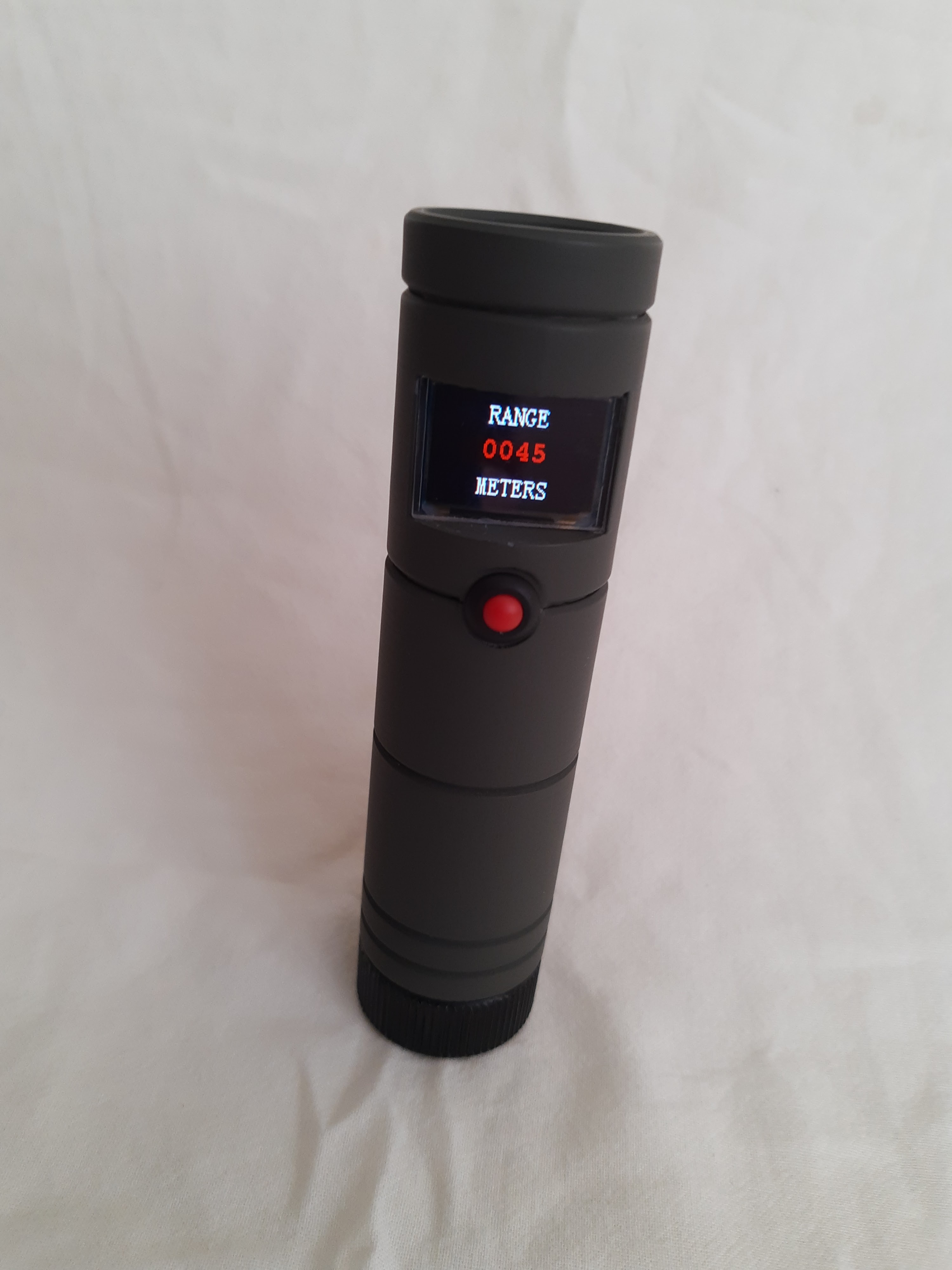
With the need to make another tracker, I opted for a canon prop replica, but one that doesn't inherently tie it to anything: the PDT locator from Aliens.

A lot of UKLTA games happen in our High Frontier game setting, which is broadly Aliens/Predator/Outland/Space Above & Beyond grungy evil corporations and monsters in space sci-fi.

Which makes an Aliens prop work nicely but the PDT locator is also very generic, it's just a dull tube that shows the distance to something on a display and beeps. So it won't stick out in any modern/sci-fi game. It could function to find a person wearing a tracker or equally be a geiger counter or locator for a stash of equipment.

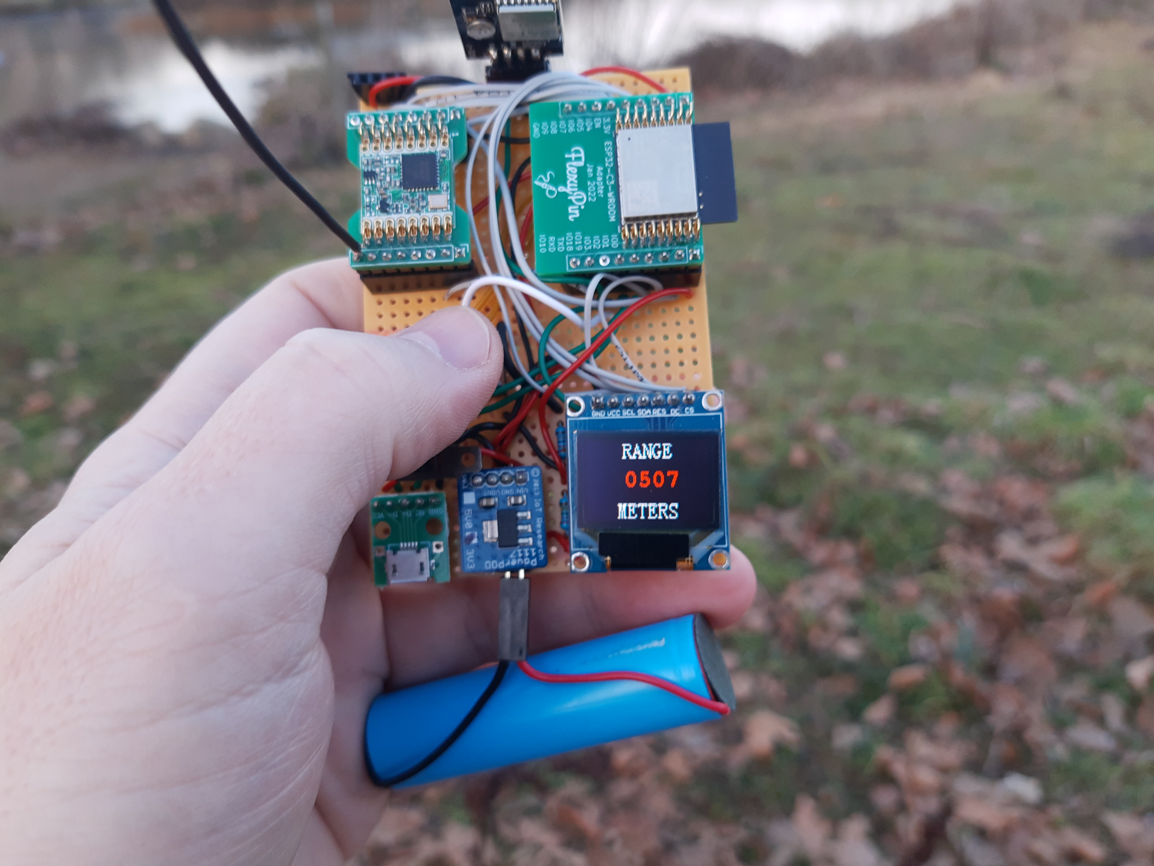
Since I built the Supernatural props, LoRa has emerged as a cheap and viable long range data radio technology. It's also standards based so not likely to disappear any time soon. I've used an RFM95W module in this, which is the default cheap LoRa module used by 'makers'. It's connected over SPI and handles all the basic LoRa Tx/Rx stuff while also feeding back information about received signal strength etc. Sending data from one device to another is really quite simple but you have to be a good citizen and not transmit too frequently. LoRa comes with rules about duty cycle/spreading factor/power that you should stick to. I've tried to minimise my transmissions but haven't yet actually checked if what I've written complies.

We've also had an explosion in more powerful microcontrollers, I've used an ESP32-C3, which means I can configure the device with a little web interface over WiFi. Should I get around to writing the software using the ESP32-C3 would also allow it to detect Bluetooth tracking beacons and I've got a stash of these, so I intend to have a go at that.

I think the ESP32-C3 is becoming my go-to microcontroller even if something doesn't explicitly need WiFi connectivity. It has a great mix of features and just enough GPIO to get stuff done. With WiFi switched off it still uses more power than some microcontrollers but clocked down to 10Mhz is about the same as a traditional AVR Arduino. Then when you need to configure something you can temporarily turn up the clock, connect to WiFi and have a proper user interface from your phone or PC.

Despite the enclosure being oversize in comparison to the movie prop, mostly to accommodate the display and keep the proportions looking OK, the electronics were still going to be a tight fit.

This led me to order a custom PCB from JLCPCB that combined most of the modules together in a compact manner.

This shrunk everything down an awful lot, with the heart of it squeezing directly behind the display.

With the bulk of the space inside the tube free I easily managed to fit a decent size recovered LiPo cell from a discarded vape, a TP4056 protect/charge board and USB socket for programming.

The end result has come out pretty much exactly how I'd hoped. Minimum order quantity for the PCBs was five, so I may build a second PDT locator on principle.

The only thing I'm unhappy with is how the colour OLED display is not massively bright. In sunlight the glare on the acrylic used to prevent damage means you need to shade it to read it. So it's better for night games, but that's fine as it's getting a first run out in a night game.

I used a colour OLED instead of a fixed 7-segment LED display from the original prop specifically to make it more flexible long term. I plan to find some larger, 'digital clock' style fonts to make it look more like the original. The currents fonts and UI are just a bit of a placeholder to allow me to test with.

So far I've tested it out to 150m from a beacon and it's fine, which is all the range I need for it. With LoRa, even with the slightly compromised wire antenna inside the case I'm expecting it to hit 200m+.


The user interface only needs to be very basic for end users, as I've written a little web configuration page to set it up more fully for games. The step up from traditional Arduino AVR dev boards in these projects to ESP32 boards really opens up so many capabilities while not increasing the cost.


For now I'm testing using beacons assembled on breadboards, but I will probably assemble the other tracker PCBs I ordered to function as beacons in our game next month. This doesn't preclude later turning them into more trackers by soldering on a display.

Going back to HUDs with a readymade display

 After mixed results with a stripped OLED display, I've got another reason to make a heads up display. This time it's to show video from a drone camera in a way that doesn't completely obscure your vision.

I've got a set of cheap Eachine goggles with built in receiver that works fine for testing but the final prop needs to be a wearable that fits in with the rest of the costume and isn't too bulky.

There seem to be essentially two models of 'moncular' video display available cheaply on Aliexpress and this was the one that was slightly cheaper at the time I ordered. It also benefits from a nice adjustment knob on one side, but lacks the flexible rubber eyepiece of the other unit.After a large number of iterations and test prints I've finally got an enclosure I'm happy to build a first prototype with.

The two halves click together using the mounting prongs on the display, hold pretty firm and I've managed to hold the PCB and easily damaged flexible flat cable in place. On the rear is a spot for a heat set insert, which I'll use to add to the arm connected to the helmet.

The final article has turned out quite nicely when printed. It looks massive but when you realise the scale of the display itself you can see it's just brought it up to a size that you can grab with your fingers and manipulate.

It needs a couple of M2.5 screws to properly secure the PCB but unless you really yank on it you're not going to accidentally damage the FFC any more.


An open source prop: Part 1

After going to Alone: Discord LARP I ended up chatting with the organisers on social media. They had some 'hackable locks' in the game that worked OK but were really just touching a couple of pads with a wire to make a beep and change an LED.

There were several game organisers playing and chat turned to making a generic 'hackable lock' for modern/sci-fi LARPs. It's something lots of LARPs will have needed or reinvented over the years. We might use them ourselves in March.

So I'm now smashing away at code for a generic lock prop based around the old favourite of an RC522 RFID reader, WeMOS D1 mini, LEDs and a piezo sounder.

The plan is to totally open source everything, with a build guide, 3D printed case, software that is pretty flexible and can be tweaked to behave in different ways.

This has already spawned two Arduino libraries. A tap code library for taking input codes on a single button (for hacking/admin) and an RFID authorisation library. The big plan is for a Web Portal interface, probably using ESPUI again.

Churning out some libraries means the main chunk of code for the prop is much less spaghetti-like and the libraries should be eminently re-usable. I really need to do this with lots of other things I've made or started to make.

Oh and obviously the Cyberdeck prop is on hold again, with no game to use it at for a while.


Mixing my ESP-Now mesh, ESPUI and physical objects in a LARP experience

As I've mentioned before, all the stuff I work on tends to be to make props for Live Action Role Playing (LARP) events. LARP comes in many flavours but the variant I'm involved in has people solving problems and fighting skirmishes with Lasertag weapons as part of a collaborative story, usually with a science fiction element.

With the arrival of the pandemic, almost all LARP except that which was conducted via video chat went on hiatus, including a game we'd been planning for a couple of years.

However things kicked off again for us on the weekend of 3-5 September 2021 with an 'anthology event' that consisted of several short games. After a chat with one of the game organisers I agreed to set up some stuff to round their Cyberpunk themed game out.

We play on exclusively outdoor sites, almost always with no access to mains power or permanent Internet service so everything needs to be self-sufficient for the duration of the game. Also with only a couple of hours of setup time available it needed to go out quick and dirty right beforehand.

I put together several elements that got included in the game, spread across three different locations on the site.


Chindōgu - part 3

I've been tempted for some time to do my planned updates to the Chindōgu, adding sound and more importantly, trying to throw together some code that avoids using Ekiga in the graphical desktop. The Pi Zero really struggles running the desktop and graphical applications but is fine when throwing stuff straight at the framebuffer.

Some research suggests it's possible to spin up OMX player wrapped in such a way it'll play a network stream straight from a camera and I'm going to try and use that for the video at least.

Coincidentally, there's currently a Hackaday retro competition and I think this could make an acceptable entry, if I get the software together and have several all talking to each other. I've accumulated multiple Sony Watchmen and Pi Zero Ws to do the build with.

To get started I've pinned out the main components on a board as it's otherwise hard to work on. One thing I want to do is get the image as decent as it can be and these horizontal gun CRTs were always dodgy.

Lacking a service manual I've worked out the function of the trimmers by trial and error.

  • RV501 - Vertical size
  • RV502 - Horizontal hold
  • RV503 - Keystone adjustment
  • RV504 - Horizontal size
Tweaking the framebuffer settings on the Pi Zero and tweaking these has made the display almost usable. With is set to 320x240 you can actually read the command line.

Recycling an old laptop into a Command Centre: Part 3

Having decided that Raspberry Pi Zeroes running the PiGFX bare metal kernel was the way forward with the small displays, I created some 3D printed 'backpacks' for the unit.

With the addition of some BNC to Phono adapters it works very nicely.

In order to talk to PiGFX you need to use the UART on the Pi Zeroes and I was going to homebrew something from cheap FTDI boards but then ordered some USB CDC boards from 8086.net. They're cheap and do the job perfectly and tidier than I'd have managed.

The 'backpack' mounts directly on the BNC socket and I think has come out quite tidily. In the very unlikely event somebody wants to do something similar, I've stuck the design on Thingiverse.


Transparent HUD using ST3375S SPI display: Part 4

I spent a little time with my 3D printer and soldering iron to make this into a more practical testbed.

As I've been working on the project, it's become very clear to me that trying to hold the screen in front of an eye while testing it just doesn't work. You just can't hold it steady enough and you end up looking at the screen rather than 'through' it, because it's moving. 

For the helmetcam project I've been making them to fit to a FAST helmet copy as they're a cheap standard piece of milsim-looking kit. So it made sense to do the same with the HUD. The bracket I've made sticks out too far to be safe walking around as you'd catch it on things, but it does a pretty good job of holding the screen in about the right place to work.

I did a little looking around with it fitted and I think I'm making good progress. You can see the image on the screen without it blocking your vision badly. It's blurred, because you're not focused on it but large icons and blocks are very recognisable.

However it doesn't work well enough yet, there are a few things that have obvious scope for improvement.

  • I need a more appropriate test pattern than the Adafruit example code and to make it updateable OTA.
  • The black frame is intrusive. I need to print it in translucent material, which I don't currently have any of.
  • Shortening the PCB would help with clearance from my face and glasses. I have already desoldered the SD reader from the rear and I think I can simply saw a section off without cutting any tracks used by the display.
There are also some things I can't easily fix immediately, without buying another screen.

  • The 'white' parts of the screen are a bit dark, so it doesn't work well indoors.
  • The screen is a bit small, it really should cover more of the field of view.
  • There is an area of permanent black round the edge of the usable display area.
I'm going to continue to slowly chip away at this over time as I still think the idea has merit, especially when tied into the camera and other communications gear I have planned.

Transparent HUD using ST3375S SPI display: Part 3

I spent a little time soldering up a Wemos D1 Mini to the transparent display and put it on the end of a tube with another little 3D printed bracket.

Nothing much new to see but it does make holding it out in front to look 'through' easier.

Tomorrow I'll design and print a bracket that will allow me to attach it to a helmet and play with angles and distance from my face.

The USB cable was just for convenient power supply, my plan is that the battery will be at the base with wires passed up the tube.

Recycling an old laptop into a Command Centre: Part 2

One of the things I want to do with this prop is have multiple screens. A primary one then the three small composite displays that used to be part of a video production setup.

With no way to slot extra display cards into a laptop, my first thought was to use a USB-VGA adaptor then a VGA-Composite convertor so I picked one up from Amazon for only £6. Even before purchase it was clear it would be a bit sucky over USB2, but that doesn't matter for a mostly text display.

It arrived and actually I'm quite impressed with it. Yes it only does 800x600x8 over USB2 but it does work (at least in Windows) even if it's not going to be any use for things like video. I can actually see myself using this with my laptop (which has USB3) for an extra screen. The messy thing is that it's not well supported under Linux, seemingly needing extra kernel drivers that don't work in current kernels etc. at which point I got discouraged. It also looks like you can only use one. Maybe. I plugged it into an Ubuntu 20.04 box and couldn't get any life from it but resolved to fiddle around with the drivers in a few days.


This got overtaken by serendipity when Hackaday reminded me of the existence of the PiGFX project, as used in the RC2014 retro computer. I'd not paid a lot of attention to it when it appeared as it just looked like a way to piggyback a Raspberry Pi Zero onto the board. Which it is, but I hadn't appreciated the software is a 'bare metal' kernel that stops it being a full Linux system and makes it into a 'dumb terminal' listening on the Pi UART and displaying on an HDMI or composite display. A quick play on my desk showed it looks the part, so I soldered up cables to the composite outputs of a couple of Zeroes and tried it with the small rackmount screens.

That's the hard part taken care of and while poking around the Pimoroni site ordering a Zero for the third screen I spotted 8086.net make a USB-UART shim specifically for them and they're cheap. This covers the other half of the job with a readymade board so once the parts show up I'll have three serial terminals connected to the laptop by USB.

There's a big overlap here with my work on creating a library for controlling this kind of terminal from a microcontroller, so coming up with code to drive them won't be new ground. It's a shame they're not full graphical displays but it will make them very easy to spit status info out to. If I need graphics I can go back to investigating the USB-VGA adapters.

Transparent HUD using ST3375S SPI display: Part 2

I had a go at fitting the light spreading film in the frame of the transparent screen. This is a really fiddly thing, it took several attempts to get the LEDs snug up to the film and everything in place.

The result is disappointing. In order to make the film spread the light well, it has a 'milled' surface. This means it makes the display less transparent as it blurs everything to more of an extent than I expected when you look through it. Then once lit, the milling creates a moiré pattern with the pixel grid of the display and makes the images look bad.

As you can see in this photo it does make the screen work in low light nicely but makes the display such that looking 'through' it is pretty poor. I'm going to abandon this idea.

Transparent HUD using ST3375S SPI display: Part 1

For some time I have fancied making a HUD (heads up display) of some kind, probably attached to a variant of the helmetcam project. Real HUDs or wearable displays that don't completely cover your face are hard, just look at how Google Glass didn't really take off.

Nonetheless it's a sci-fi trope and I fancy a go at it. My vague plan is a transparent display you look through and don't focus on, a bit like some kinds of gunsight. It's not going to be able to show text, but it may work for blocky colour coded contextual information.

To have a stab at this I picked up a couple of cheap 1.8" ST3375S SPI displays, commonly sold for use in microcontroller projects like weather stations etc. They're very cheap and I bought two, in case I broke one. Having a second intact one to code on will be useful too.

The first step is to peel the whole display from the PCB. It's simply held on with sticky foam pads and luckily on this specific board there are no components to be careful of, just the ribbon cable. A different module might not be the same though. I used a thin plastic scraper pushed slowly but firmly between the PCB and screen to remove it.

Once the screen is free from the PCB you need to separate it from the backlight. Luckily the white plastic surround is very thin and if you gently flex it this will unclip from the the screen.

The backlight is still attached to the ribbon cable so be careful not to rip it while you do this.

The LED backlight is inconvenient so I stripped it further. There are four parts, the white plastic surround, a thin piece of clear plastic film to spread the light, a thin white paper-like diffuser and the LEDs.

The first three parts are very lightly stuck together and you can carefully peel it apart until you're just left with the two backlight LEDs soldered directly on a section of the ribbon cable, which doesn't get in the way too much.

The bare screen is quite dark but when you hold it up to the light you can see the individual pixels which looks quite cool.

Once I'd got it to this point, I did a little measuring and 3D printed a surround to hold the screen safely while I tinkered. After an initial false start, I got the Adafruit ST3375S library example code driving the screen and as I'd hoped, big blocky images are quite legible while looking through the display.

The next step will be gluing a D1 mini to the PCB and point-to-point wiring it to the screen so I can play around with holding it in front of my face on a stick.

Without a backlight it's totally useless in anything but bright light. It may be possible to re-use the light spreading film and have the LEDs provide a little light on the display, for which I'll need to design a different surround for the screen.


Recycling an old laptop into a Command Centre: Part 1

I have, for some time had a plan to build a portable 'command centre' prop which has a generic PC inside but has that industrial look often seen in action movies. A friend asked me to dispose of an old dead laptop so I stripped it down and made it work.

This laptop was a good candidate for this as it was one of those bulky OEMed machines that use a generic motherboard with various components on little daughterboards. It was dead because the PSU socket had been smashed but as this was a discrete socket clipped into the case, fixing it up was easy.

It's too old to be much use with modern software but a stripped down Linux install works just fine.

Over a lazy afternoon I carefully stripped out all the modules, including taking the webcam and microphone out of the screen surround and it's now ready for when I get the time to build the physical enclosure. I'm particularly pleased with how bright and clear the screen is after a careful clean, initially it looked dismal.

My plan is to use this ridiculous stainless steel waterproof keyboard/trackball combo I bought some years back as part of the prop.

I'd also like to use this set of rackmount monitors, but they take a composite input.

It seems reasonable that a USB to composite out peripheral might exist but if it doesn't I can run them with some microcontrollers and maybe do a Serial to composite display that shows text you send it, a bit like a dumb terminal. throw in support for some basic ANSI control characters and I'm creating the other half of my terminal UI library.

I've seen products on Tindie that turn a VGA monitor into a proper VT100 compatible terminal but nothing for composite and I'd need it to connect over USB anyway. I have a small stash of composite displays I've picked up over the years and creating something to drive them would be good. It could be easily argued that a Raspberry Pi Zero is a better way to do this but then you've got three computers to look after and I'm a fan of using microcontrollers instead.

The laptop can also drive a VGA screen for yet another display but I think that would make the prop physically too big.

ESP32-CAM helmet camera, prototype 3


While working with the ESP32-CAM board I've realised that the AMS1117 LDO fitted to it is a bit of a problem due to a 1V dropout value. This means that if you power it from an 18650 cell it starts to brown out far sooner than needed.

Coincidentally somebody from the LARP community asked me to see if I can make a design that takes four AA batteries and I put this new version together. The 6V from the battery pack works much better than the single 18650 and means they can be swapped easily but sadly makes the camera really quite bulky. Nonetheless I've sent them the files so they can have a go at building some units.

Going forward I've seen that the LDL1117 LDO only has a 0.3-0.6v dropout and is pin compatible. I think carefully desoldering the AMS117 and replacing it with one of these would solve my brownout problems.

An alternative would be a small 'daughterboard' that connects to the headers and has a buck convertor. This would be the more elegant option, especially if I managed to include the power switch and lamp button onboard. I've still not found time to see if I can make an I2S microphone work with the board, but that could also go on a 'daughterboard' if it did.

ESP32-CAM helmet camera, prototype 2


I did a little more work on the design and added an external antenna, as it's a known fact the board works better with one.

Then I put quite a lot of effort into painting it up in a basic camouflage pattern. I am very pleased with how this worked out.

No other real changes to the project but it shows you can make something decent looking at a low cost.

ESP32-CAM helmet camera, prototype 1

It's been a while since I've blogged. Back in March I was working very hard indeed on making props for our upcoming LARP. With the pandemic we suddenly had to postpone until some indeterminate time in the future.

This killed my enthusiasm for a bit and when I picked up projects again I needed a change.

Over the last couple of weeks I've been fiddling with the ESP32-CAM board again and turned the pile of components in the first photo into a working helmet camera prototype.

With the standard camera example code loaded it works really quite solidly and the battery life with a 18650 cell recovered from an old laptop battery pack seems good.

I started out with the selfie lens for aesthetic reasons but it does a good job of taking in a whole room as you move around, something the default lens these boards ship with doesn't do.

The tactile button on the side switches on the onboard 'flash' LED and there's an acrylic light pipe bringing the light out of the shadow of the lens. It's not a proper long throw torch but it just about manages to light a dark room so you can see and the camera will generate a very grainy picture with the gain up full.

Onboard charging is nice but currently getting the cell in/out in the field is impractically fiddly and the holder is stuck in with tape. The indicator LEDs on the TP4056 board are brought out on the side with another couple of light pipes and these work great. The idea is if these were issued on a multi-day game it would be the player responsibility to keep them charged and a USB charging socket makes that practical. For a short game they probably won't need charging.

Overall this has worked out really nicely and the design I've done in OpenSCAD is modular enough it's easy to swap out the rail mount and add something different. These could easily double as 'CCTV' cameras with a ball socket mount.

The design does need a little more work to make it easy to assemble but broadly it's there. I've also had it suggested that an external antenna would be acceptable, when I thought it would be too ugly. So I'll work on a version with that over the next few weeks, the boards have a uFL connector and it'll really help increase range.

I've got enough camera boards and recovered batteries in good condition to build a set for a whole team of 'marines' and a few static CCTV units. Doing this while keeping the cost down for 10+ units has been a major requirement of this project and I've definitely succeeded at that. The bill of materials using the recovered 18650s comes in at about £7 plus printer filament at the moment.

Mesh networked computer terminals with RFID logon - part 6

Going back a few weeks I was having trouble with stability of the RFID readers. Which I've now fixed with a far less complicated solution.

The library has an option to turn the RFID antenna on and off. Simply shutting it off and turning back on to check the card periodically seems a 100% stable solution.

Obviously you should also check the card hasn't been swapped by checking the ID hasn't changed but here is a a minimal sketch to do this. As checking for a card stops it appearing as new it's easy to get the logic messed up but this is a tested and working example.

Note to self: start putting stuff on GutHub.


#include <SPI.h>
#include <MFRC522.h>

const uint8_t SS_PIN = D8;    //My example code is for a WeMos D1 mini, change these to match your setup
const uint8_t RST_PIN = D0;   //My example code is for a WeMos D1 mini, change these to match your setup
 
MFRC522 rfid(SS_PIN, RST_PIN);

bool cardPresentWhenLastChecked = false;
bool antennaEnabled = true;
uint32_t cardCheckTimer = 0;

void setup()
  Serial.begin(115200);
  SPI.begin();
  rfid.PCD_Init();
  Serial.println(F("Checking for RFID card removal"));
}
 
void loop()
{
  if(millis() > cardCheckTimer)
  {
    //Start a check of the card
    if(antennaEnabled == false)
    {
        //Turn the antenna back on
        rfid.PCD_AntennaOn();
        antennaEnabled = true;
        //It takes time to wake up the RFID card so the sketch needs to wait before checking for it
        cardCheckTimer = millis() + 20ul;
    }
    else if(antennaEnabled == true)
    {
      if(millis() > cardCheckTimer)
      {
        //Check for a card after a delay for it to power up
        if(rfid.PICC_IsNewCardPresent() == true)
        {
          if(cardPresentWhenLastChecked == false)
          {
            //Card was absent but has been presented
            Serial.println(F("Card presented"));
            cardPresentWhenLastChecked = true;
          }
        }
        else if(rfid.PICC_IsNewCardPresent() == false && cardPresentWhenLastChecked == true)
        {
          //The card was present but has been removed
          Serial.println("Card removed");
          cardPresentWhenLastChecked = false;
        }
        //Switch off the antenna, otherwise the card will not show as 'new' when checked again
        rfid.PCD_AntennaOff();
        antennaEnabled = false;
        //Wait before checking the card again
        cardCheckTimer = millis() + 100ul;
      }
    }
  }
}

Mesh networked computer terminals with RFID logon - part 5

After a chunk of work I've got file syncing working fully. The code does a simple manifest of everything on the SD card except for the irritating "System Volume Information" directory Windows puts on there if you view the card on a Windows system.

As my mesh network isn't designed to be high bandwidth and I'm not expecting the files on there to change often, this is a slow, lightweight process. After all it's only running on an ESP8266, don't expect BitTorrent.

The steps the mesh takes to sync are broadly...
  • Recursively iterate the whole file system on the SD card
  • Open each file and do a CRC16 of it
  • Store the full path and filename, size and CRC16 in a data structure
  • Write this to a simple flat file to save this across restarts. Each file is given a sequence number starting at one that increments with each change
  • Once all the files have been read, XOR all their CRC16s together and store it
  • The total number of files and this XOR of the CRC16s are advertised periodically by each node flooding the whole mesh
  • If a node receives a XOR that doesn't match its own it asks for the CRC16, size and sequence number of each file on the other node, one at a time
  • Some simple if/then/else logic decides if it needs the other node's version of the file
  • Files are transferred 64 bytes at a time in a TFTP-esque manner
  • Once the XOR and number of files match the two nodes are considered synced and stop
  • To detect change from an initially synced state, if a file is changed the new CRC16, size and sequence number are flooded to the whole mesh immediately
  • Notification of deleted files use a similar mechanism and stay in the data structure
  • There are timeouts and retries on the various steps in the process so it will fail fairly gracefully and restart
This is probably full of edge case horrors and has no way to handle file conflict resolution. I don't care, this is not an enterprise class distributed file system, it's a bunch of microcontrollers in a field that I need to have the same files on, mostly, and stay in sync, mostly.

Watch the awesome log output!


Mesh networked computer terminals with RFID logon - part 4

This is another little update, I have basic file transfers working, woohoo!

There is no authentication but some basic sanity checking of the data, ie. is the packet from the station it expects, for a file it expects and the chunk it expects next. It's pretty much like TFTP but done over my proprietary mesh network stuff.

I'm currently only shipping 64 bytes at a time, inefficiently packed too, so it's going to suck for large files but the process works and will chunk through a queue of files happily grabbing them.

Now the code needs cleaning up and to allow for things like failed transfers.

I also need to go back to the file manifest handling as it handles change, but not initial seeding. However this is a really positive step forwards.