
I don't often do 3D printed costume pieces (mostly because I hate sanding and painting 3D prints) but I'm really happy with how this came out.
I don't often do 3D printed costume pieces (mostly because I hate sanding and painting 3D prints) but I'm really happy with how this came out.

Now I'm back on this nonsense again but this time it's for a sci-fi game at Dropzone 2023.
The Supernatural props were great at the time but they had a couple of inherent problems.
A lot of UKLTA games happen in our High Frontier game setting, which is broadly Aliens/Predator/Outland/Space Above & Beyond grungy evil corporations and monsters in space sci-fi.
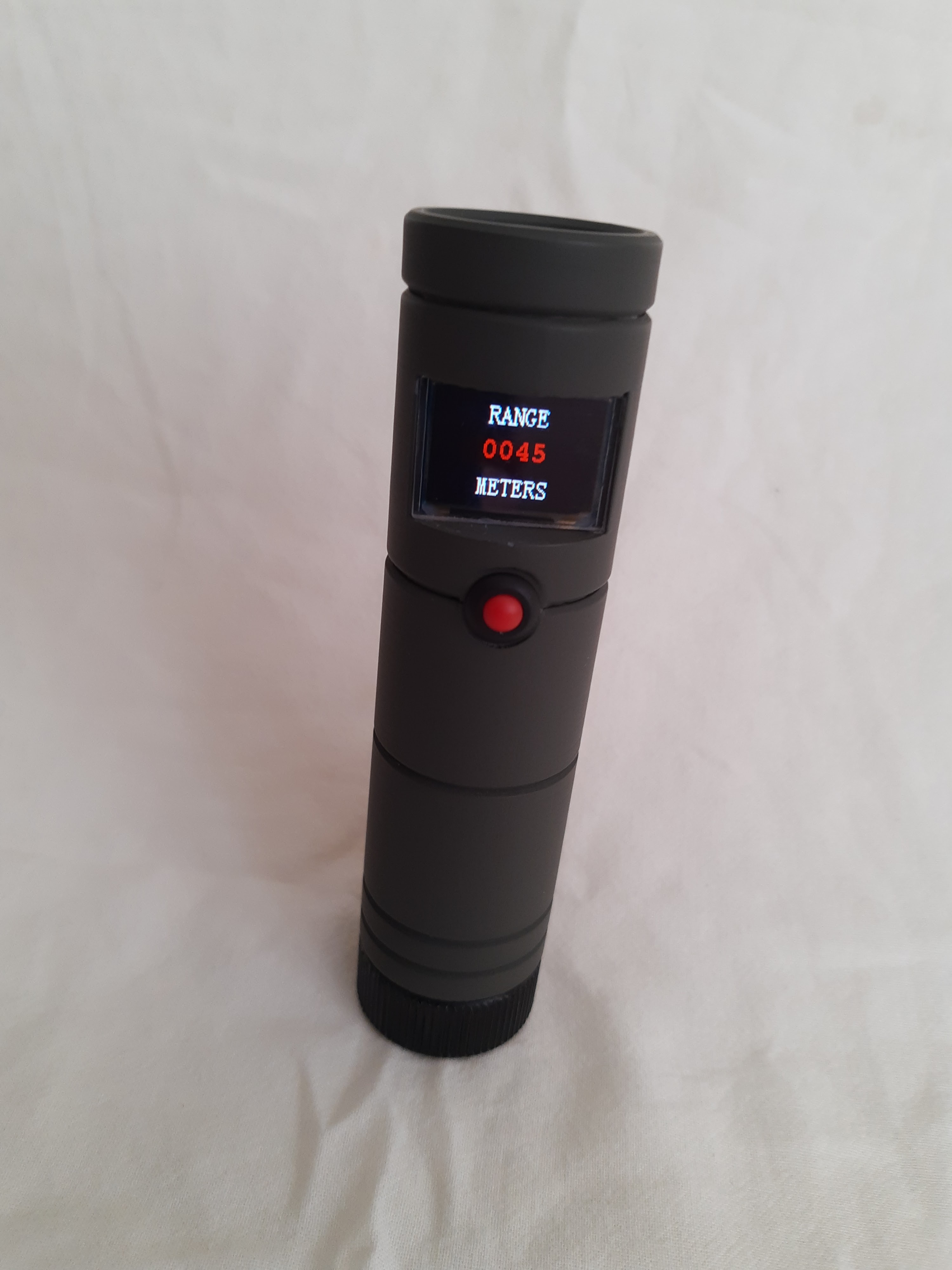
Which makes an Aliens prop work nicely but the PDT locator is also very generic, it's just a dull tube that shows the distance to something on a display and beeps. So it won't stick out in any modern/sci-fi game. It could function to find a person wearing a tracker or equally be a geiger counter or locator for a stash of equipment.
Since I built the Supernatural props, LoRa has emerged as a cheap and viable long range data radio technology. It's also standards based so not likely to disappear any time soon. I've used an RFM95W module in this, which is the default cheap LoRa module used by 'makers'. It's connected over SPI and handles all the basic LoRa Tx/Rx stuff while also feeding back information about received signal strength etc. Sending data from one device to another is really quite simple but you have to be a good citizen and not transmit too frequently. LoRa comes with rules about duty cycle/spreading factor/power that you should stick to. I've tried to minimise my transmissions but haven't yet actually checked if what I've written complies.
We've also had an explosion in more powerful microcontrollers, I've used an ESP32-C3, which means I can configure the device with a little web interface over WiFi. Should I get around to writing the software using the ESP32-C3 would also allow it to detect Bluetooth tracking beacons and I've got a stash of these, so I intend to have a go at that.
I think the ESP32-C3 is becoming my go-to microcontroller even if something doesn't explicitly need WiFi connectivity. It has a great mix of features and just enough GPIO to get stuff done. With WiFi switched off it still uses more power than some microcontrollers but clocked down to 10Mhz is about the same as a traditional AVR Arduino. Then when you need to configure something you can temporarily turn up the clock, connect to WiFi and have a proper user interface from your phone or PC.
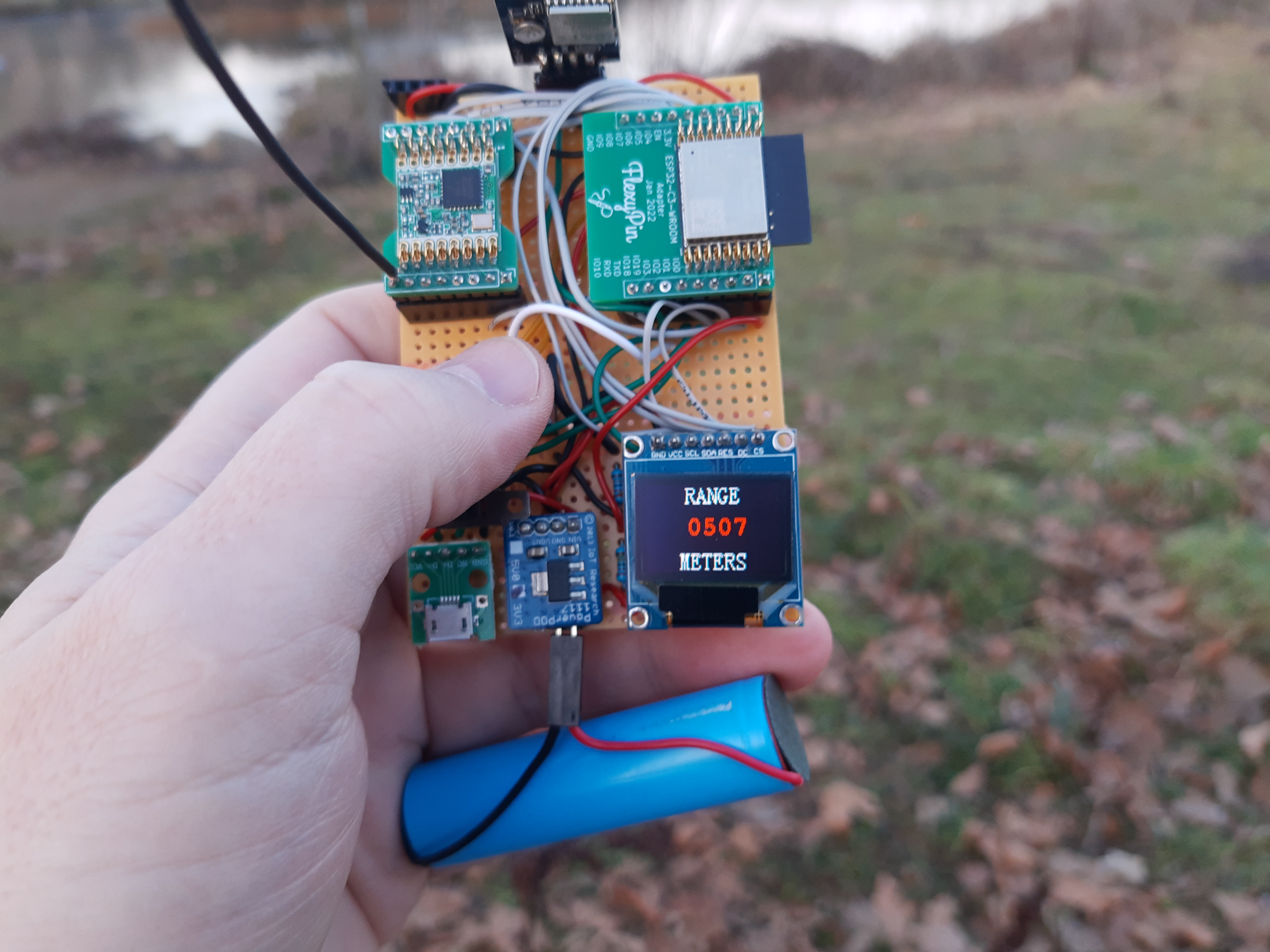
This led me to order a custom PCB from JLCPCB that combined most of the modules together in a compact manner.
This shrunk everything down an awful lot, with the heart of it squeezing directly behind the display.


All our Lasertag LARP weapons are 'homebrew' and mostly rely on a small number of people doing cottage industry builds of PCBs for them but I've previously made things of my own with Arduino Nanos and stripboard.
The barrier to committing to a 'proper' design of my own has been an inability to settle on a good solution for generating the sound. Generating the Lasertag signal is well understood but we've previously relied on bought in boards that play back uploaded samples, which have been of variable quality and sometimes a bit too quiet for my liking.
With the knowledge that the ESP32-C3 can use I2S to play back sound I've had it in my head that it should be possible to make a Lasertag board based around one. This is especially so as the ESP32-C3 also has the 'RMT' peripheral designed for IR remote control which generates signals similar to our Lasertag system in hardware.
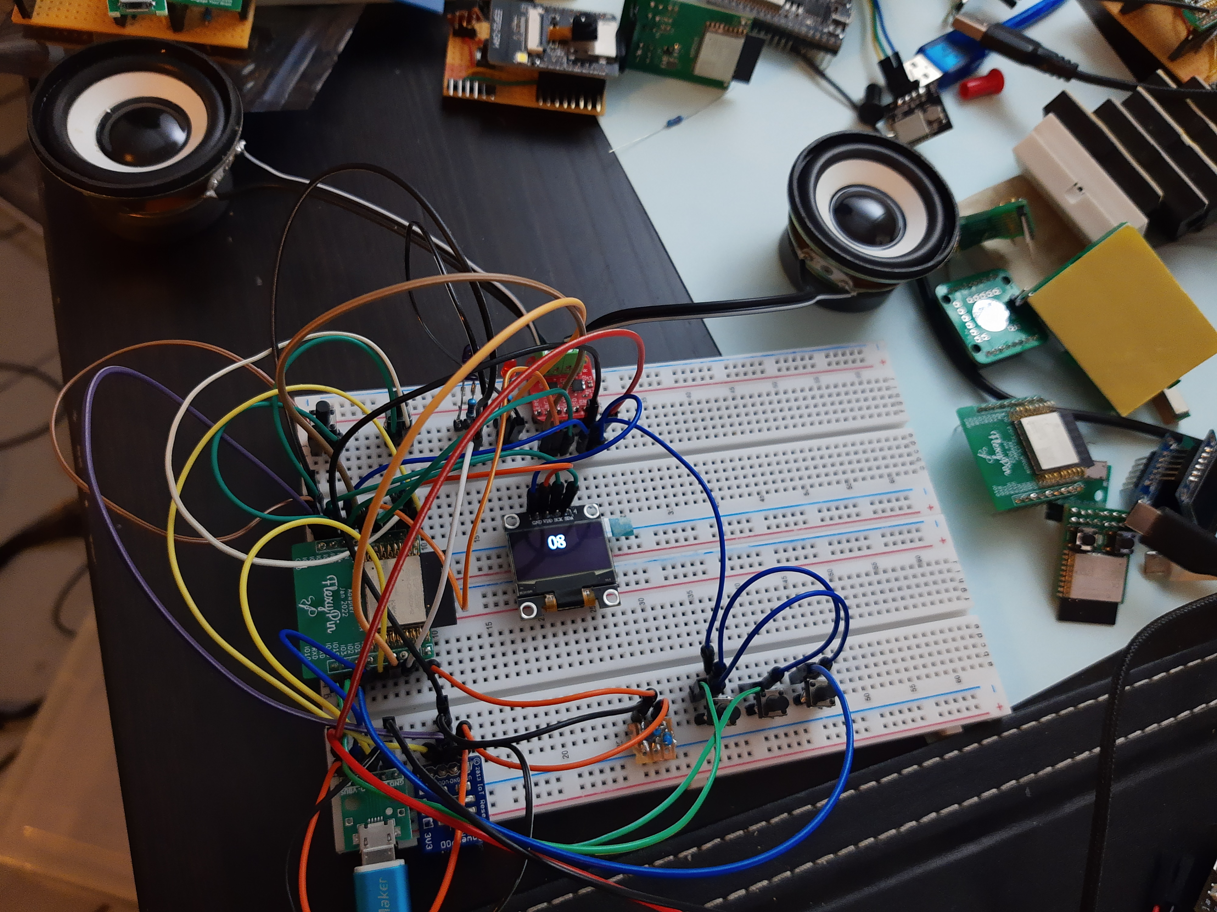
They're very much MVP boards, with an LDO for voltage regulator (not massively efficient) and the onboard lithium cell charger being a bought in TP4056 module. This will let me test the design at our next event in May, hopefully.
The desktop testing seems to work OK but real life testing will show up how well it works with other sensors and long ranges. I may have underspecified the MOSFETs and passives, but I'll find out.

One thing that is a minor irritation is the number and naming of the hardware Serial ports changes depending on whether you enable 'USB CDC on boot' and this isn't immediately obvious how to deal with.
With USB CDC on boot enabled you have...
#if ARDUINO_USB_CDC_ON_BOOT == 1#define SERIAL_DEBUG_PORT Serial#else#define SERIAL_DEBUG_PORT USBSerial#endif
You can then just use
SERIAL_DEBUG_PORT.println("Hello World");

They've all been variants on an ESP32 microcontroller, some kind of 3.3v power supply then a load of headers for the specific peripherals I want for that specific project.
My SMD soldering is a bit hit and miss, I've had a few irritating failures from creating shorts under big modules like the ESP32-WROOM or the uSD socket. I'm OK at putting solder paste on, but then I tend to very slightly botch the placement and have to nudge the module into place smearing it. I just don't have hands steady enough to get it right first time. I'm fine with the smaller components.
On the whole though it's a positive experience and I've got better at this than when I was first ordering things in 2019.
One of the things that changed since then is the proliferation of microcontrollers that have native USB support. Now there are multiple ESP32 variants with it but it's appearing all over the place, right down to the ultra-cheap RISC-V chips from WCH.
The boards above have ESP32-S2 modules but I'm also making things with the ESP32-C3, which I'm coming to really like due to low cost, native USB for programming and just enough GPIO for most things.
The upshot of this is making boards with USB naturally leads to wanting USB connectors for the boards.
Which I dislike.
Low volume electronics projects with SMD soldered micro-USB sockets have a bad history for me. I've damaged or totally ripped off the socket on more than one board and they're often just a bit cruddy. Professionally made high volume products are better but it's still a weak point.
The obvious solution is to fit USB-C, which addresses many of the issues but have you looked at the soldering footprint for one? Nope. Also I don't need USB-C. These are USB 1.1 devices with no need for Power Delivery or anything smart.
So I've embraced old-school full size USB-B connectors for the larger PCBs. They're trivial to hand solder and robust. Which is good if they're likely to get rough handling, which some of these may do. If it's going in a physically large object the extra size isn't going to matter.

The ESP32-C3 is replacing the ESP8266 in my affections and I ordered twenty of this PCB. It is effectively a small battery efficient development board. So I've reinvented the wheel a bit.
In the kind of projects where I expect to use this I often bury the main PCB inside somewhere but will want the USB socket accessible in the side of the enclosure.
Having the USB socket on a short flying lead is convenient for this and USB is more tolerant of this than you'd expect. In principle you need to match the track impedances/lengths etc. but in practice you get way with it. It adds a lot of flexibility and if the socket gets damaged it can be easily replaced.
Separating the the USB socket also means I can come up with whatever power path I want at time of build. Some things are going to have LiPo batteries and want an onboard charger. Some will have removable batteries. Some will be USB powered. These boards are generic after all.
I may come back to this and design myself a board that includes onboard power path management/charging for a single LiPo cell, which I did on an old design, but for now I'm happy with how these are coming out.